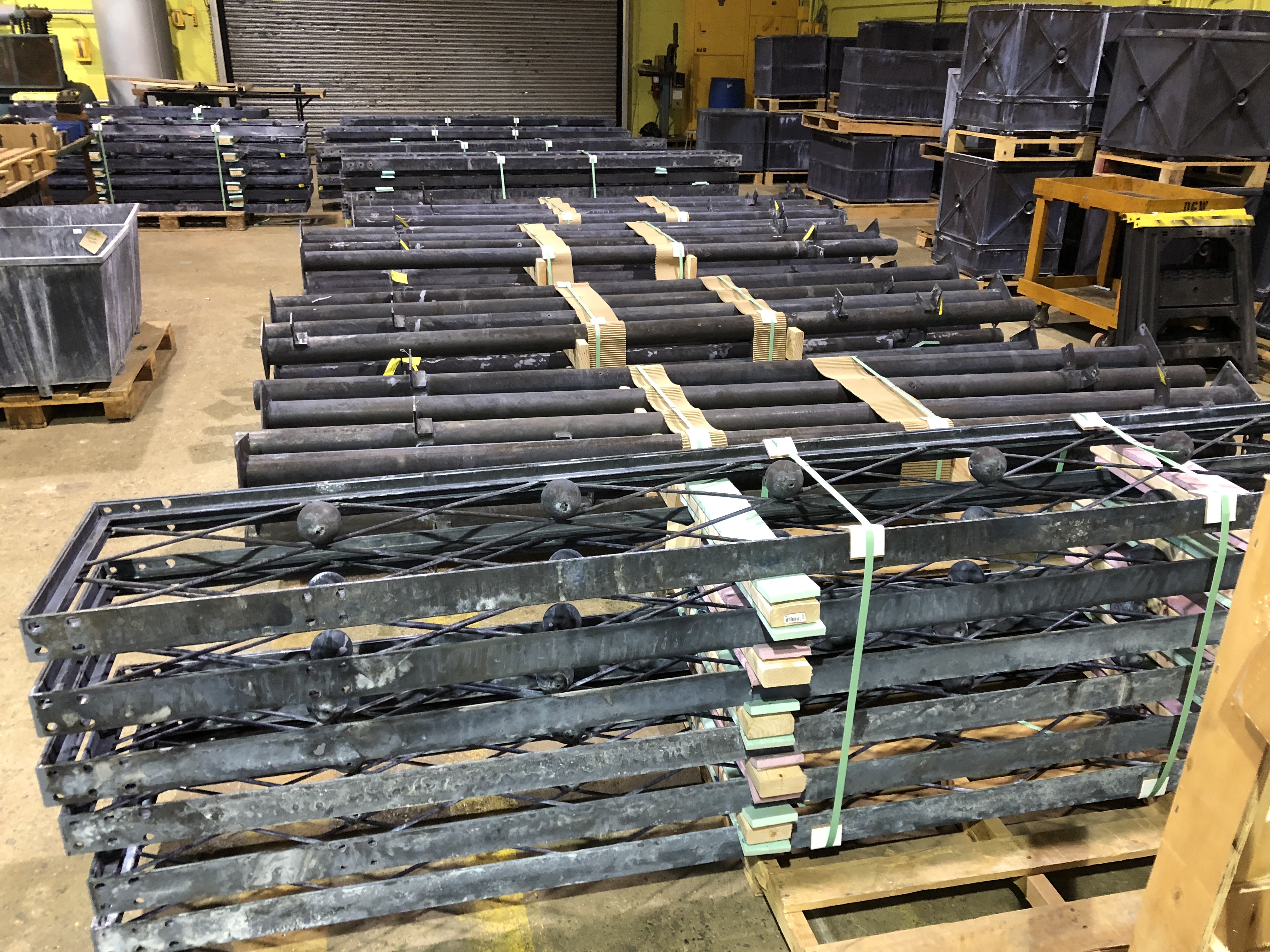
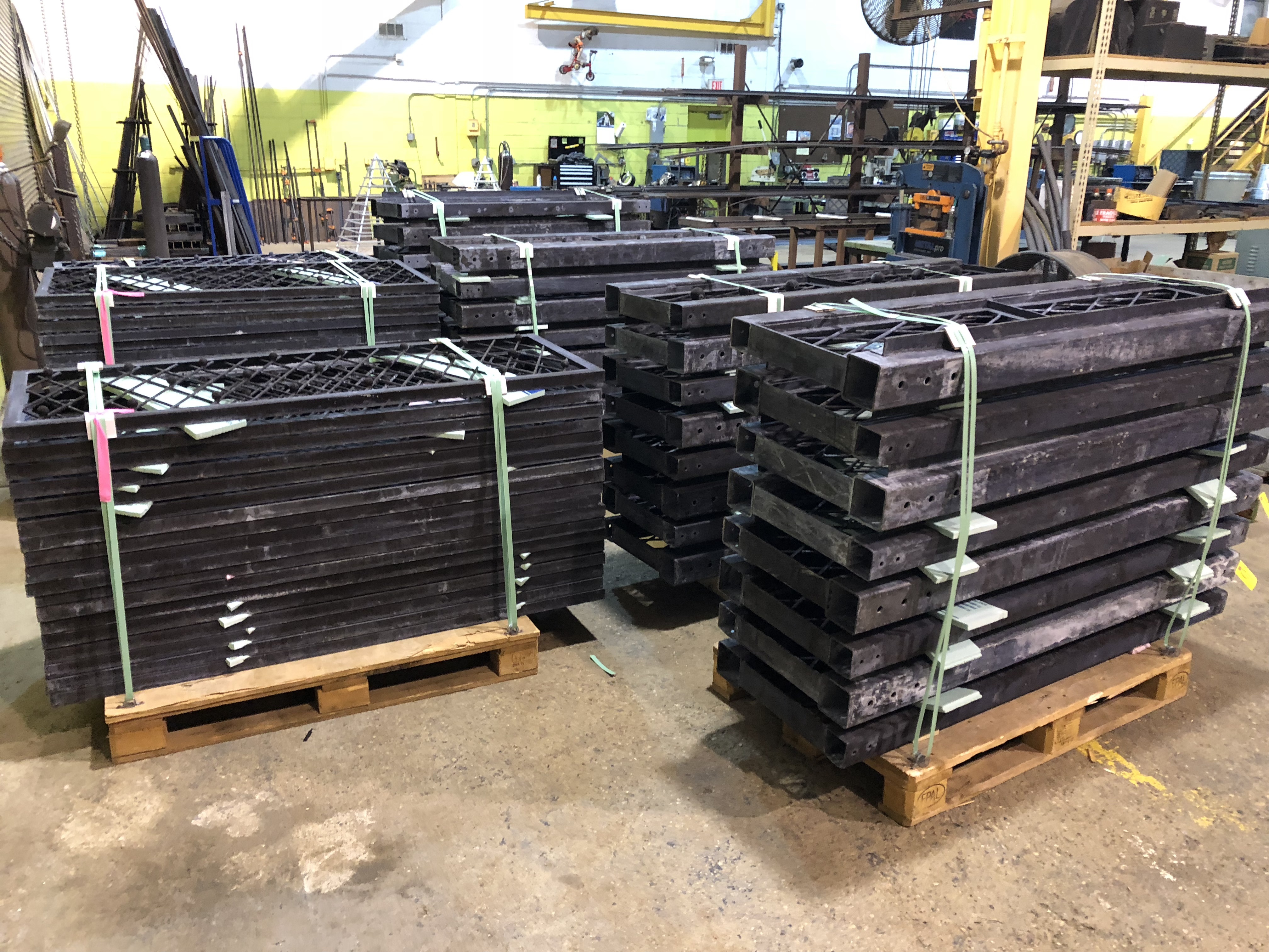
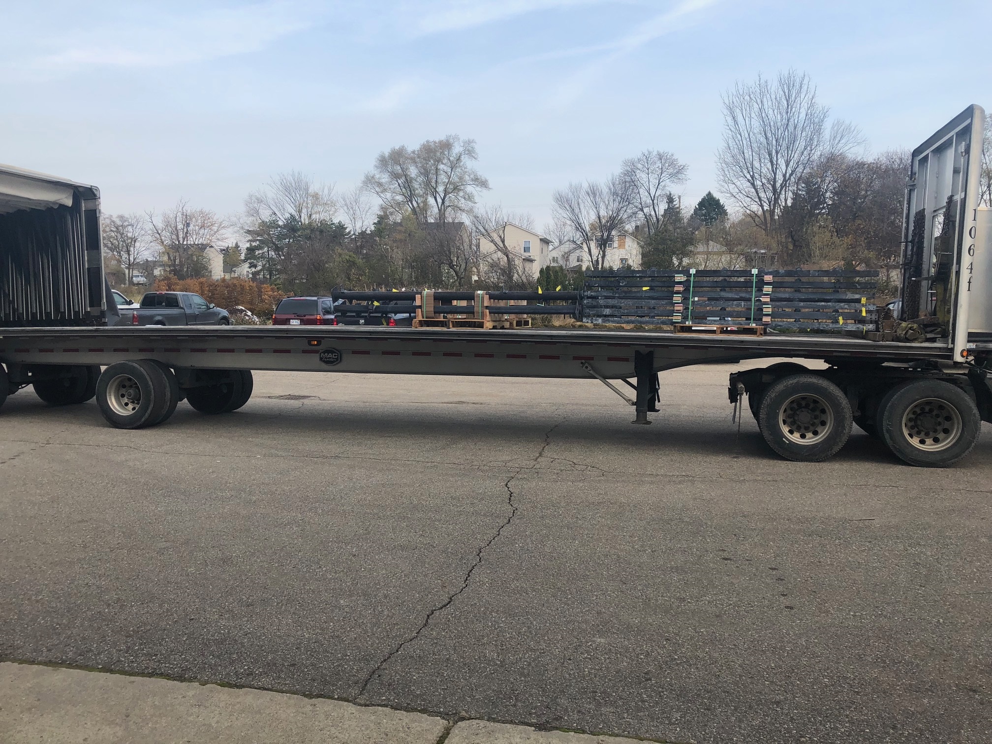
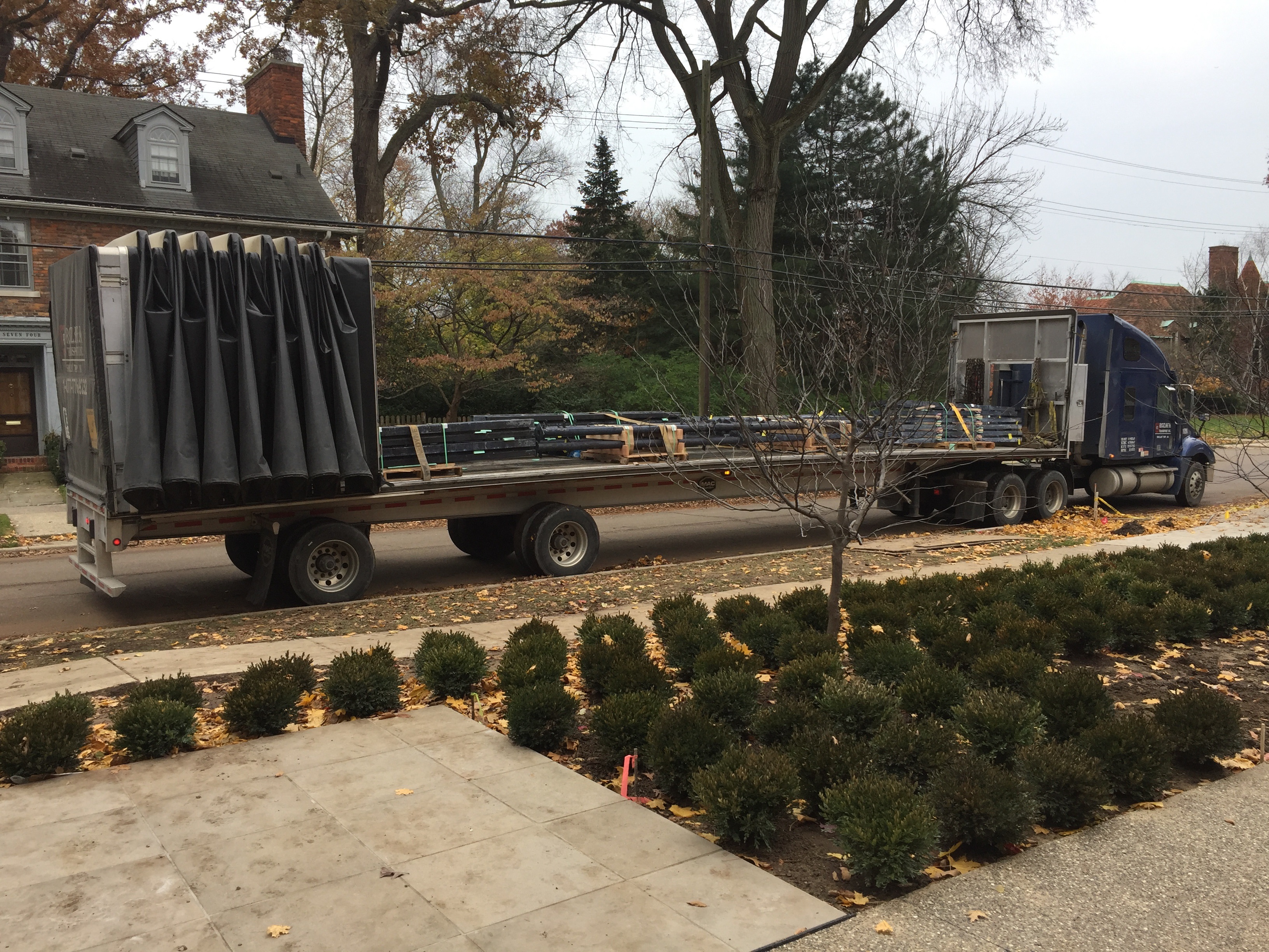
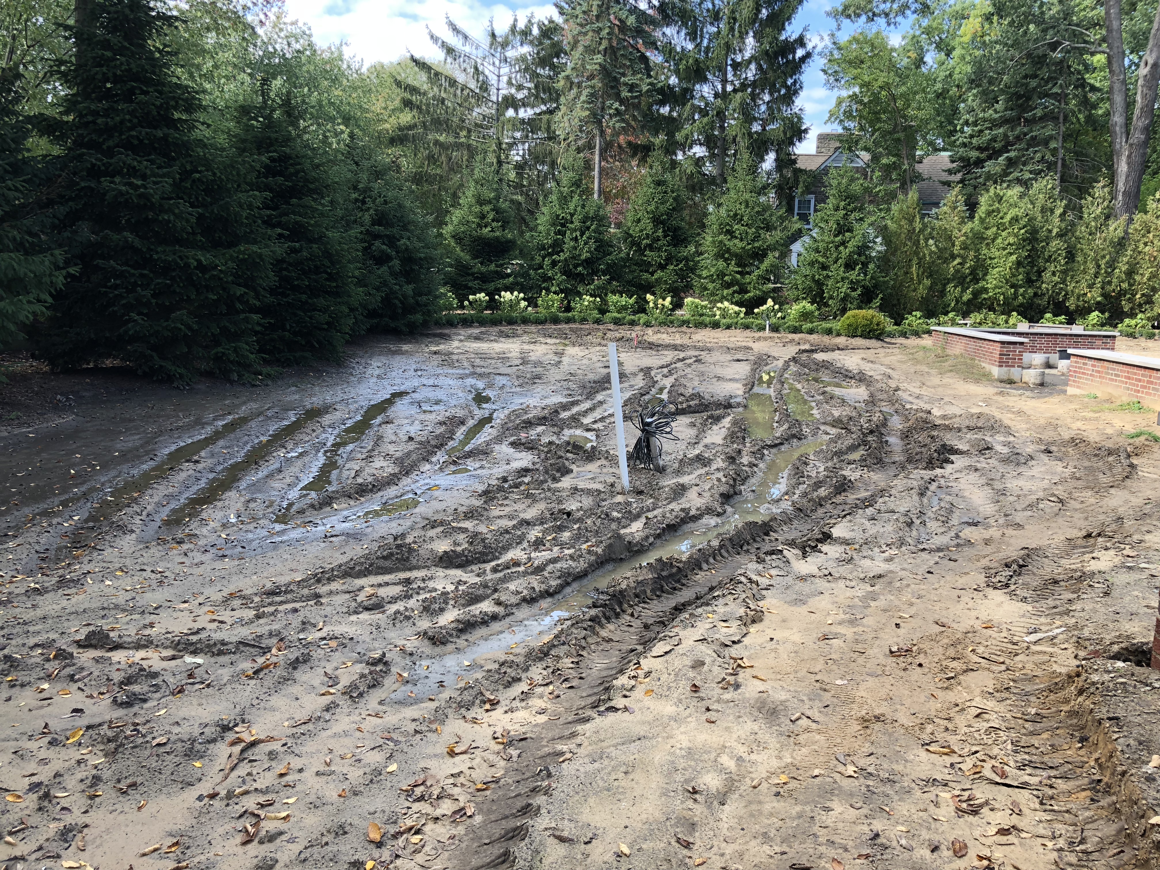
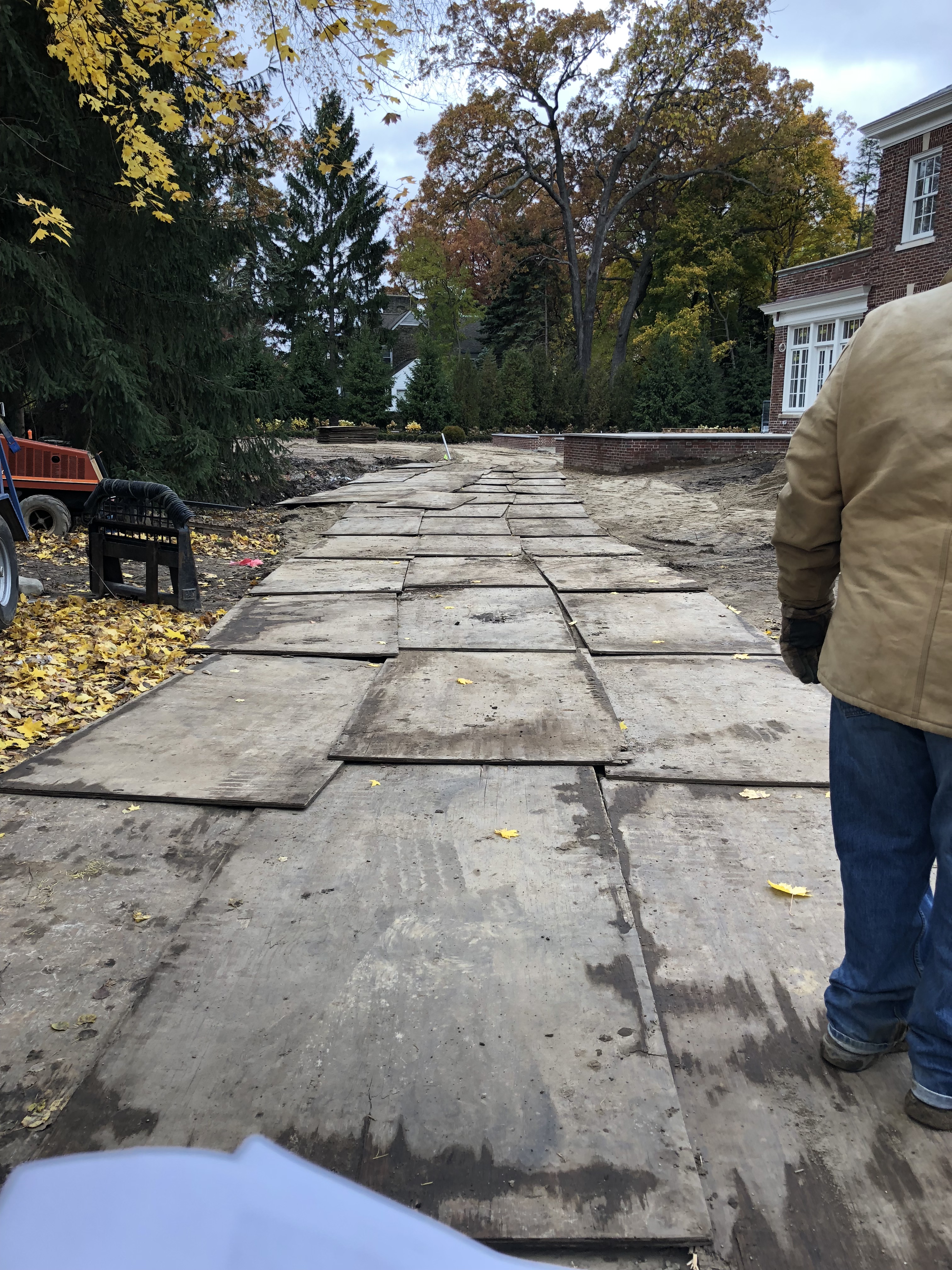
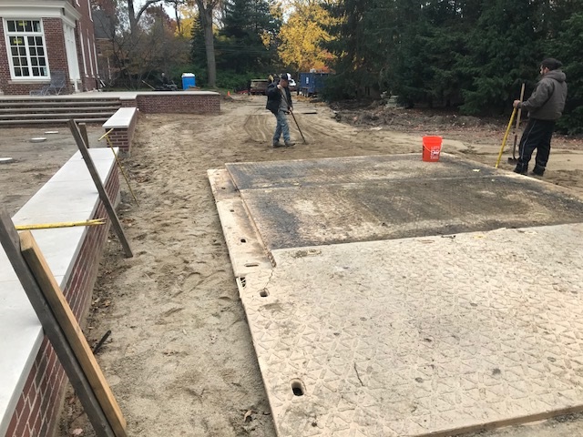
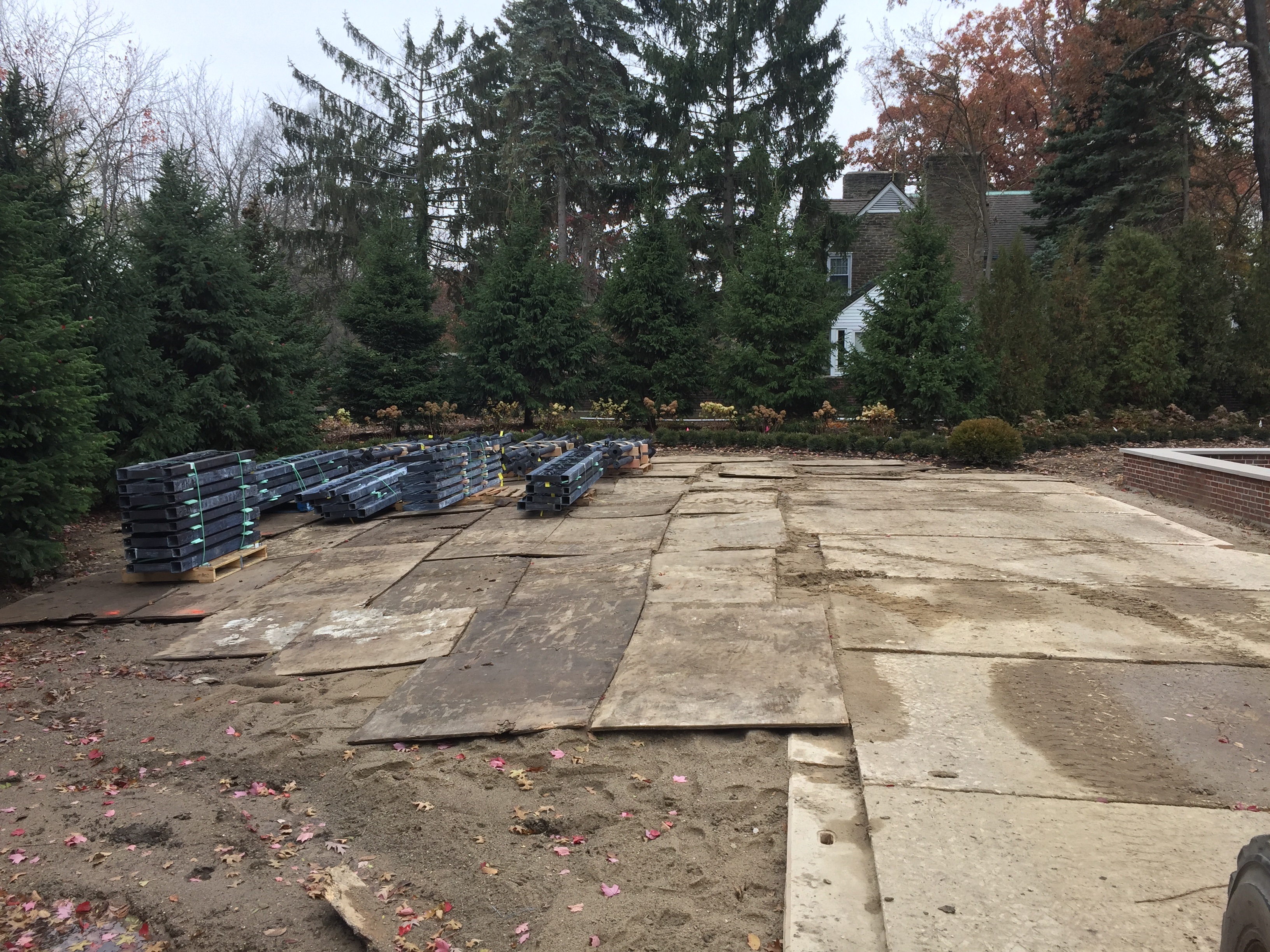
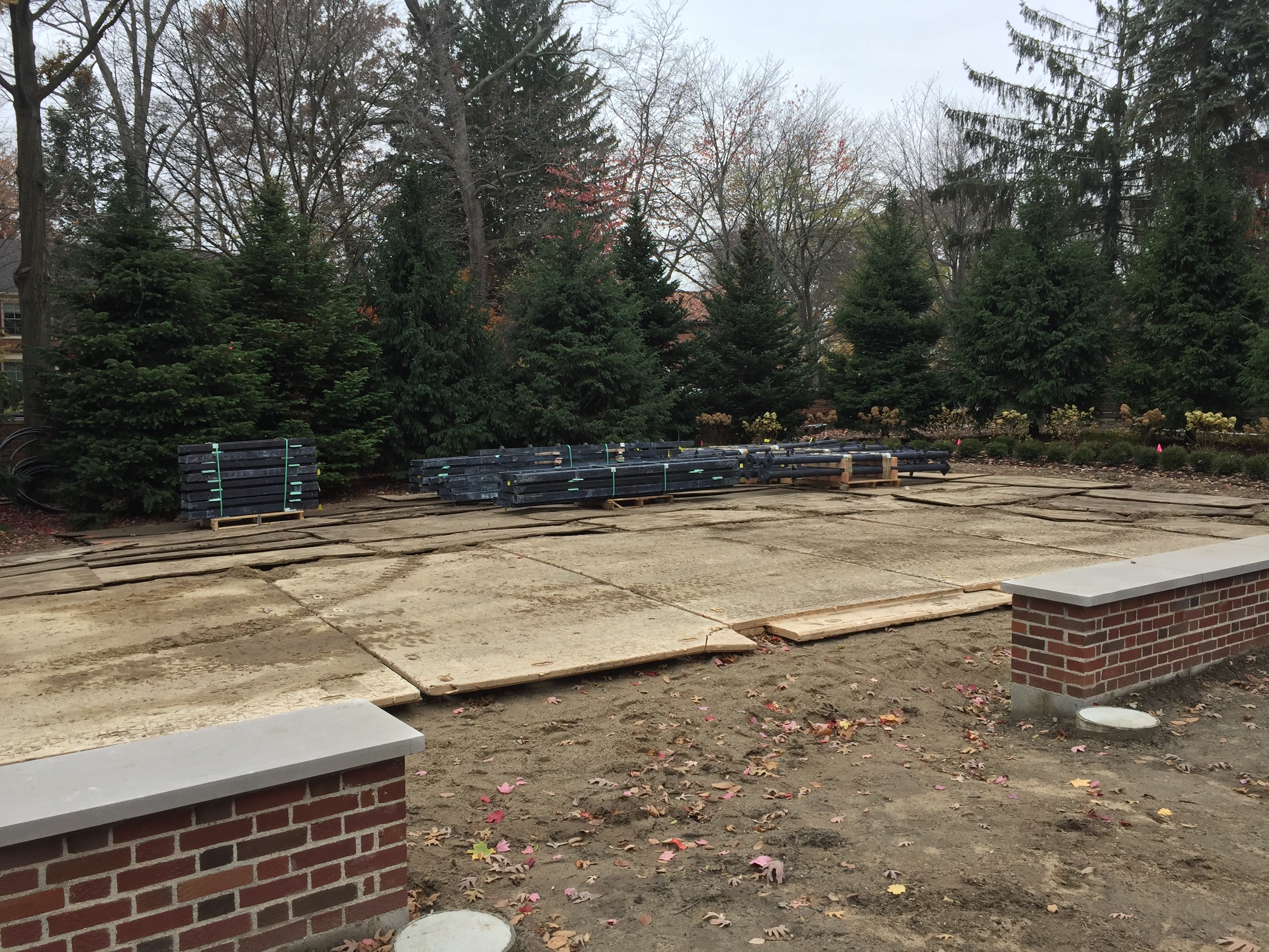
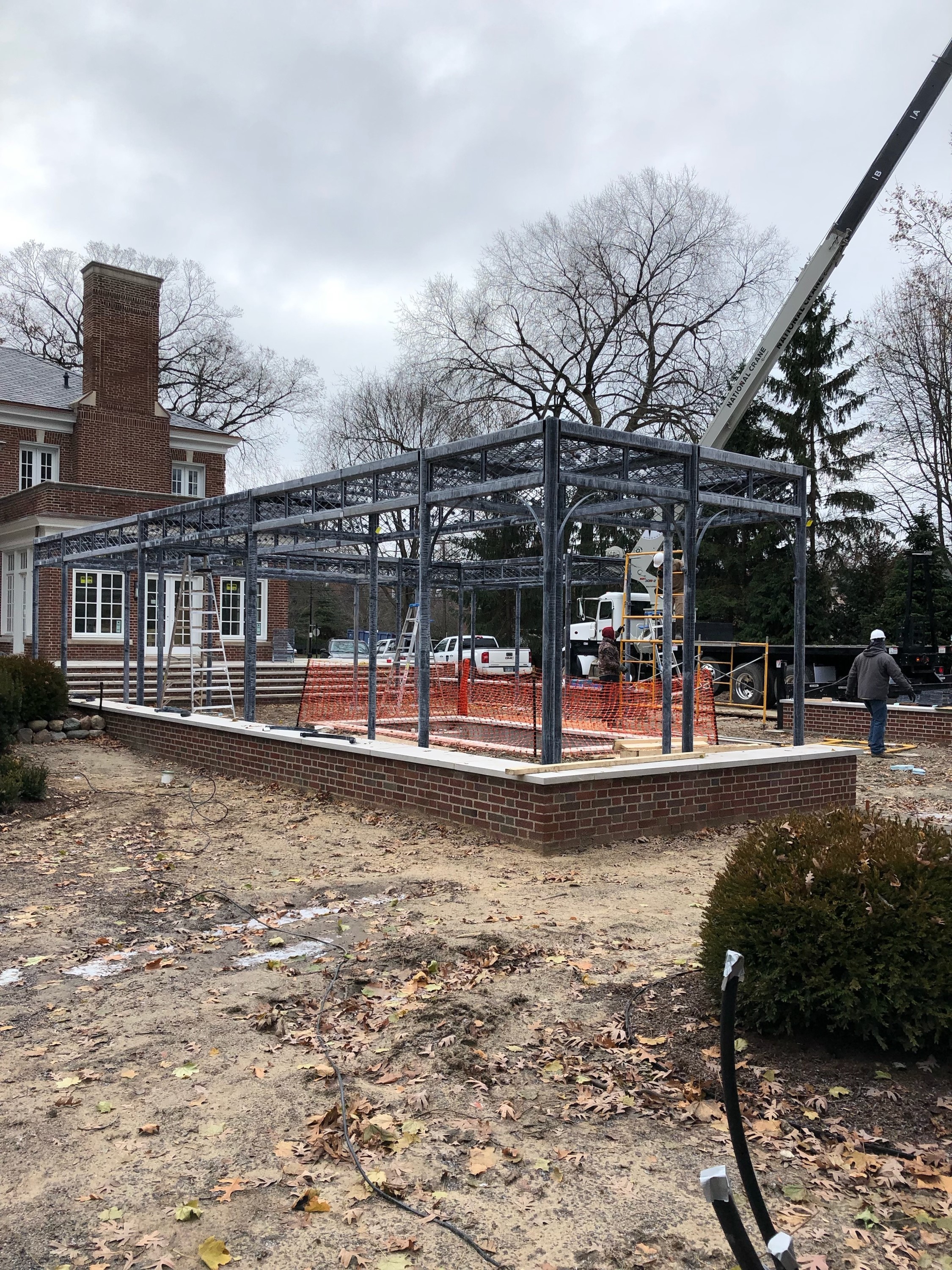
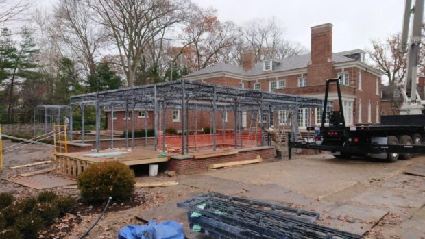
 You may not have read in November of last year a post about a landscape renovation that we have had underway since June of 2018. A part of this project in process involves the design and fabrication of a large scale cloister style pergola. The story behind the design and fabrication? Click here for the details. the design and fabrication of a steel cloister The 2018 story concluded with that moment when 18 tons of steel sections and parts finally made their way to the site for installation. Of note was the fact that wet weather necessitated building a road back to the installation site. A structure of this size had to be assembled on site, so Buck engineered it to be put together and set up one section at a time. Just before Thanksgiving, a large boom crane moved in for the duration, as each section of the structure would be far too heavy to maneuver by hand.
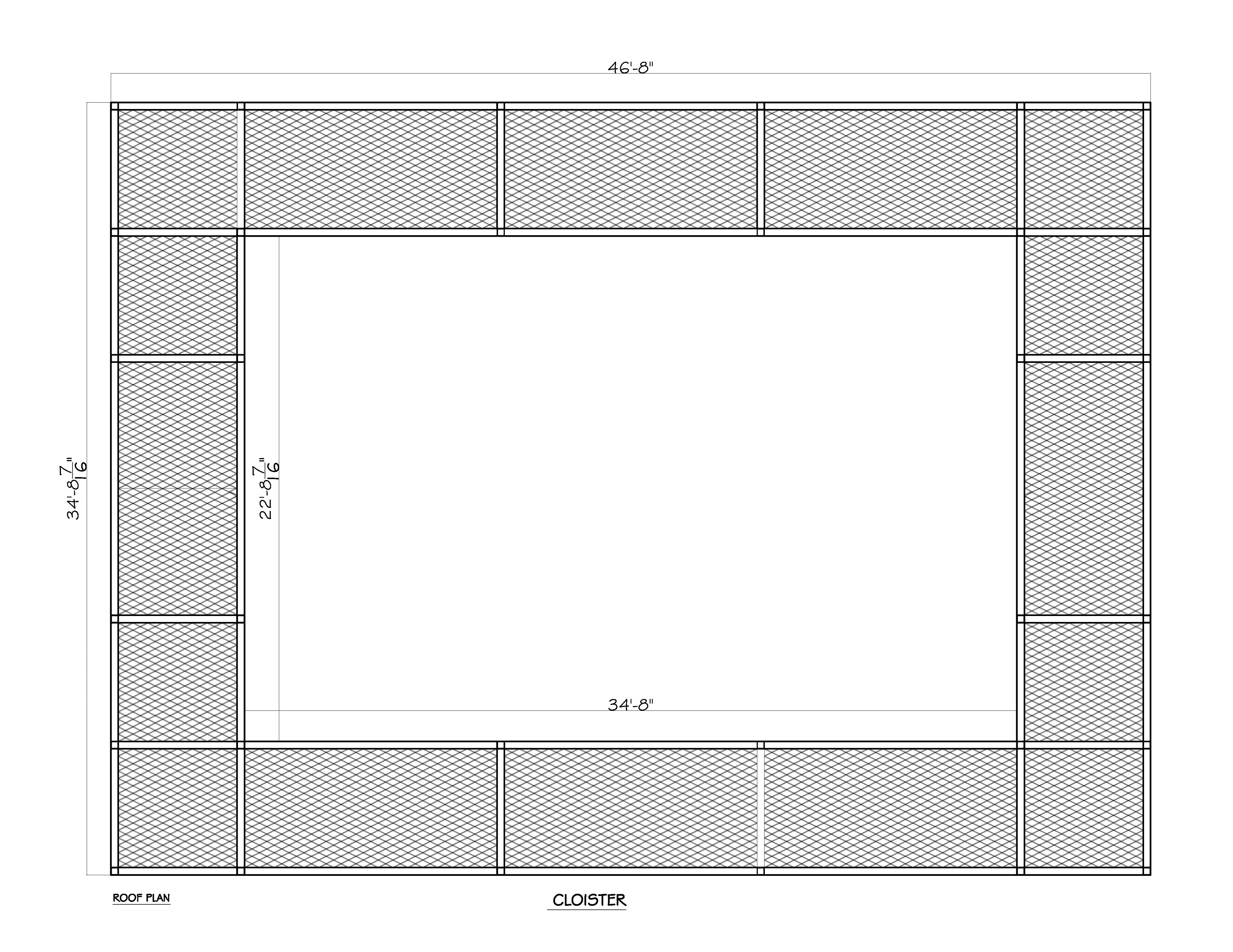
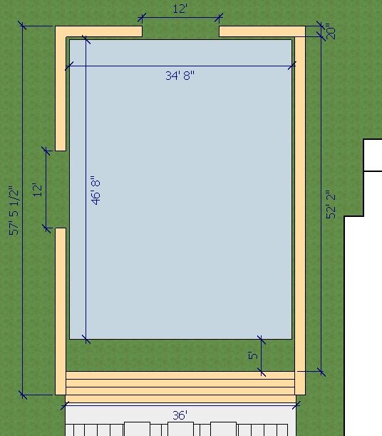
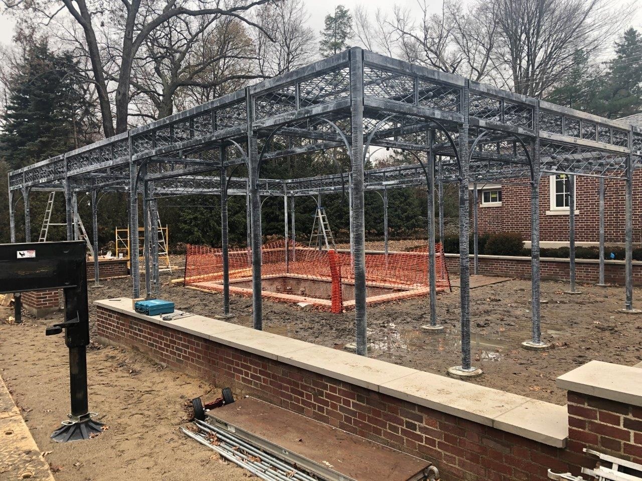
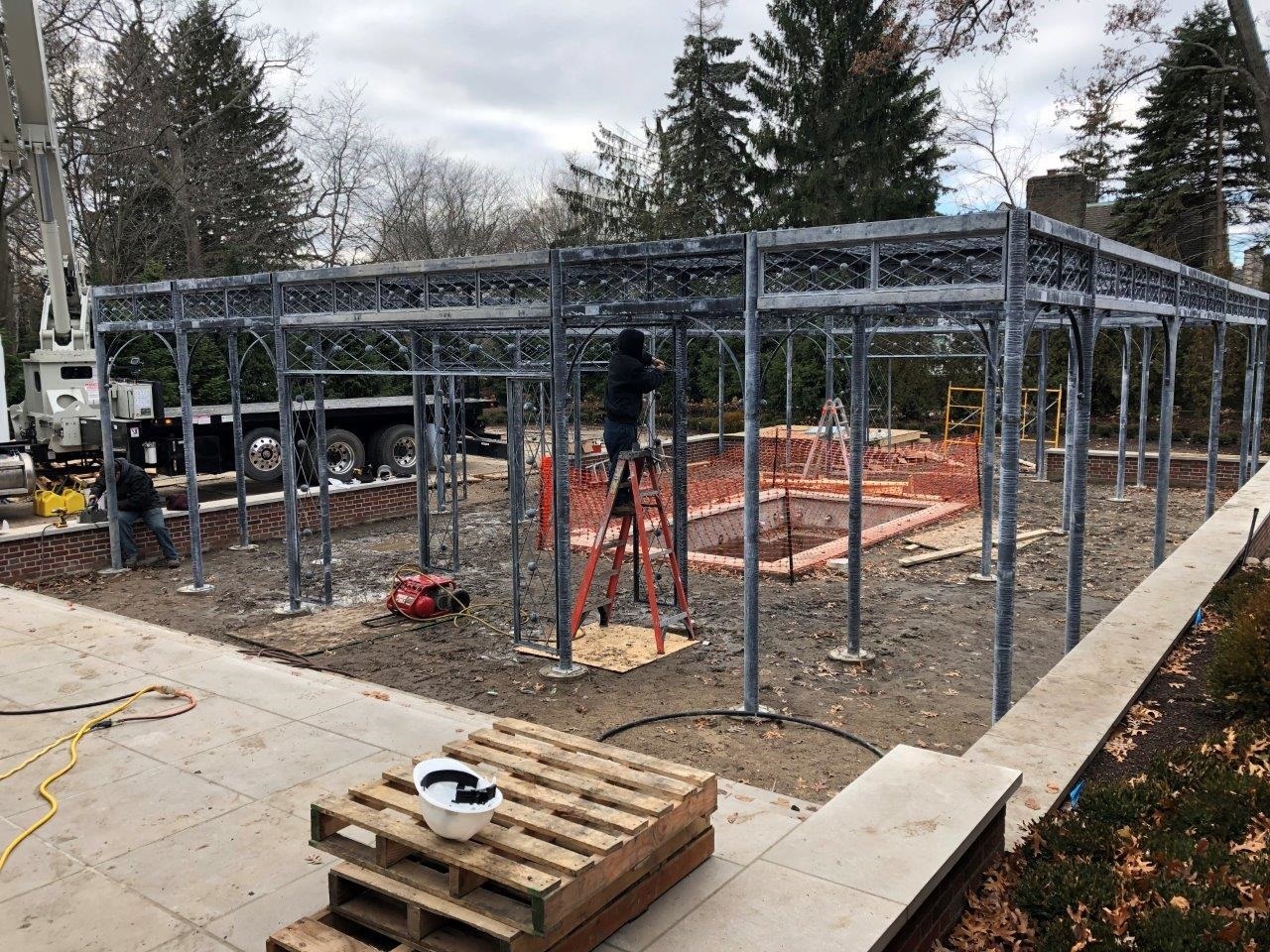
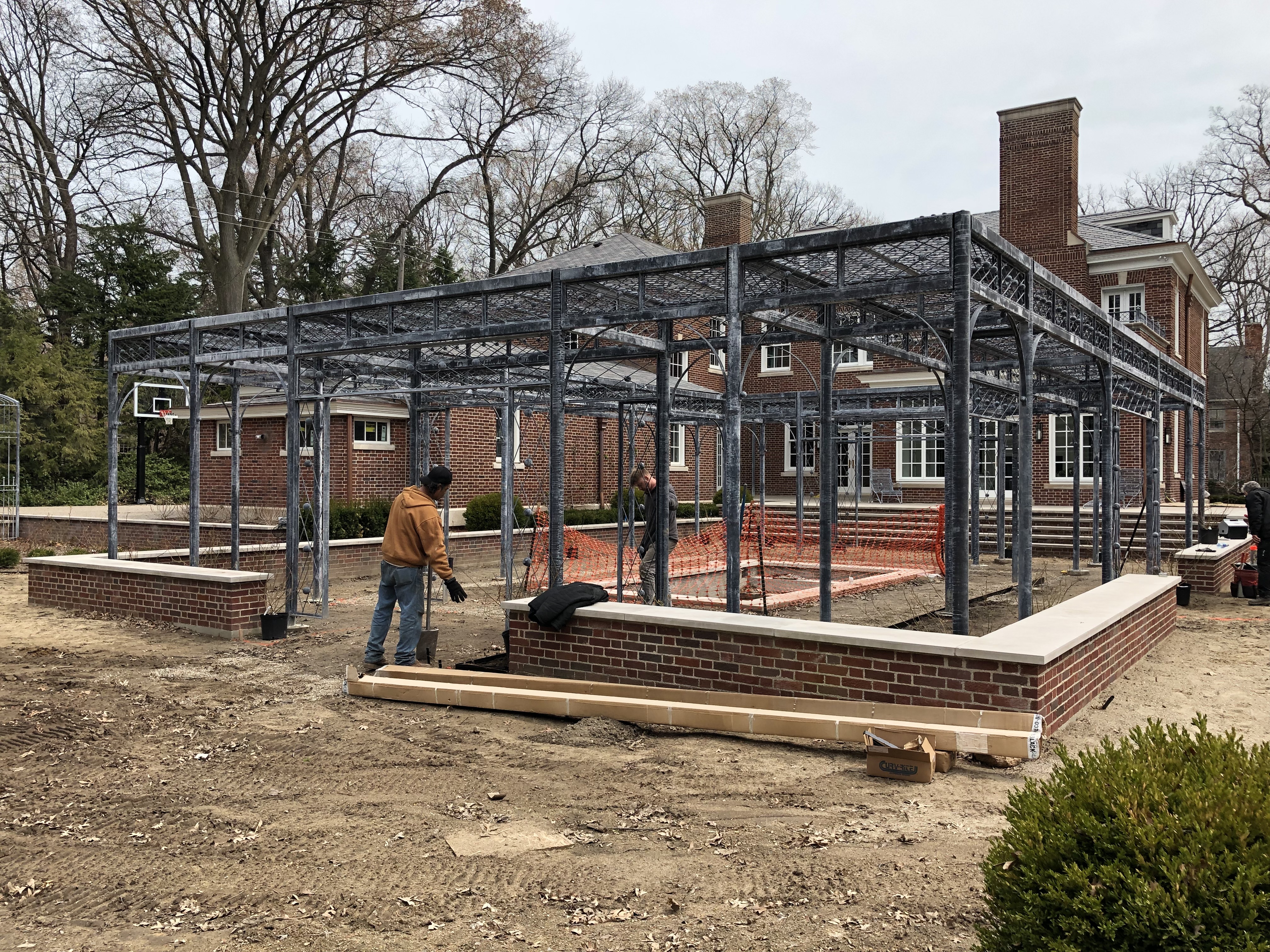
 It was slow going. The weather was bitterly cold and muddy. The finished size of this structure is 47 feet long by 36′ wide. I have no idea how many pieces there were in total, but there were enough to call the installation of this pergola a puzzle of enormous size. To make every section line up perfectly so it could be bolted to the previous section was daunting. The process made my eyes water.
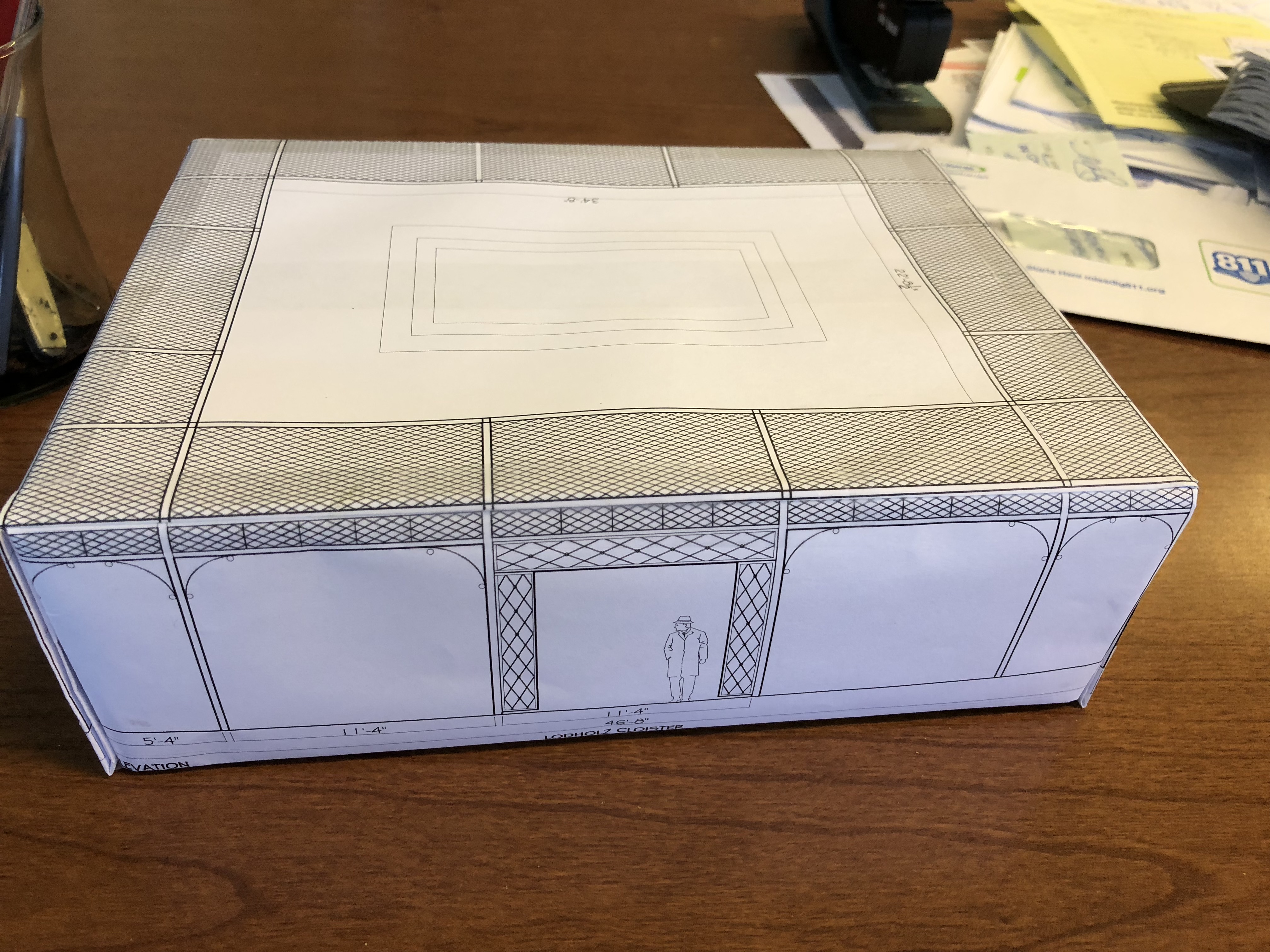
 Eventually the structure took shape. Seeing it go up was an experience like no other I have ever had as a designer. The model I built my client was the size of a piece of copy paper- 8.5″ by 11″. Of course the model did not at all describe the actual structure that was to enclose 1700 square feet. The model was a not so accurate expression of a structure as it was an attempt to express an idea of the landscape shot through with romance. What?? Romance is my middle name. Ha. As much as I admire classic French landscapes for their edited expression, and coolly compelling geometry, Italian gardens and landscapes have that element of romance that I find irresistible. As for this steel cloister, suffice it to say the design is as more about my client and her love of the garden than anything else. Though I had spent hours going over every proportion and detail, at some point I had to commit to a design. And a presentation of that design to my client. In May of last year, she decided to go ahead and build.
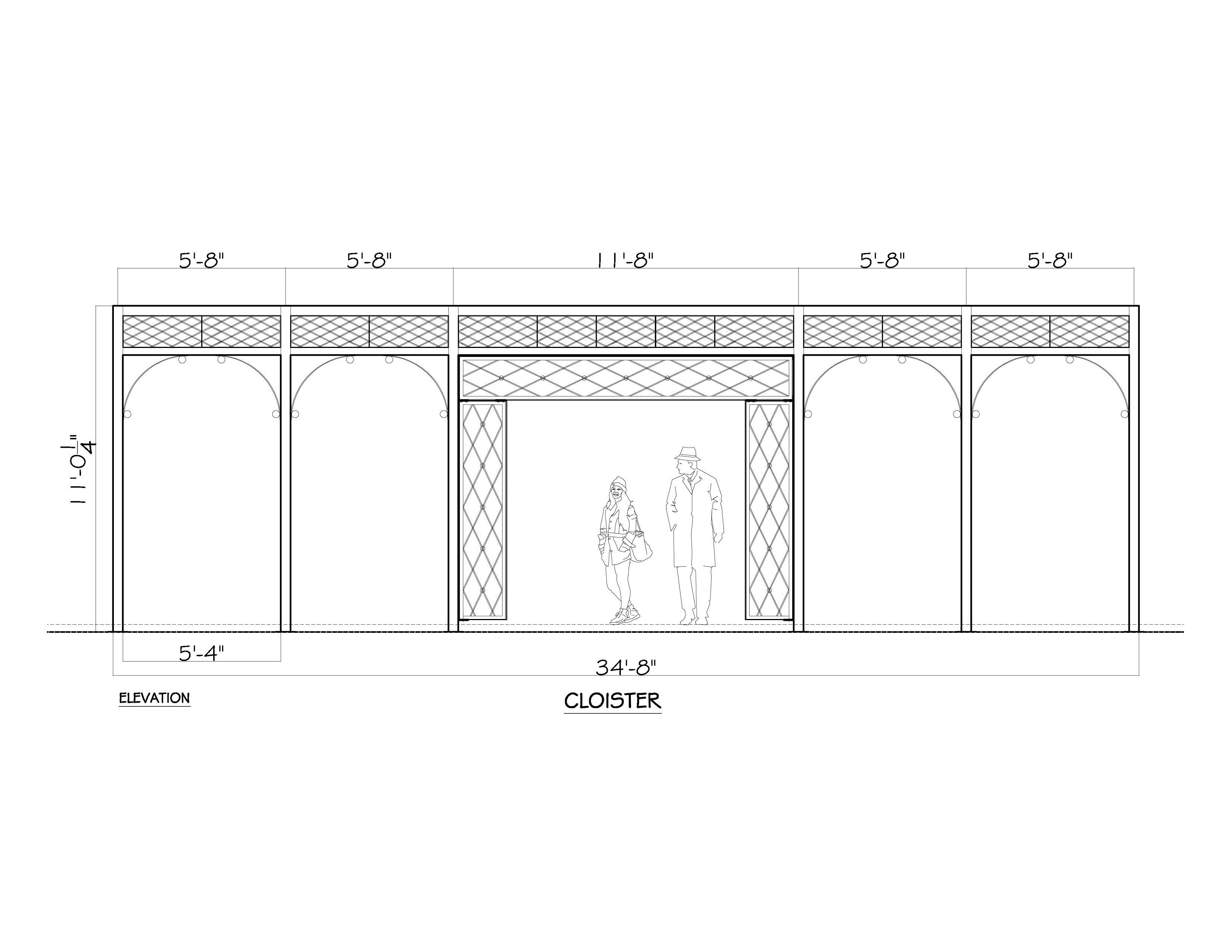
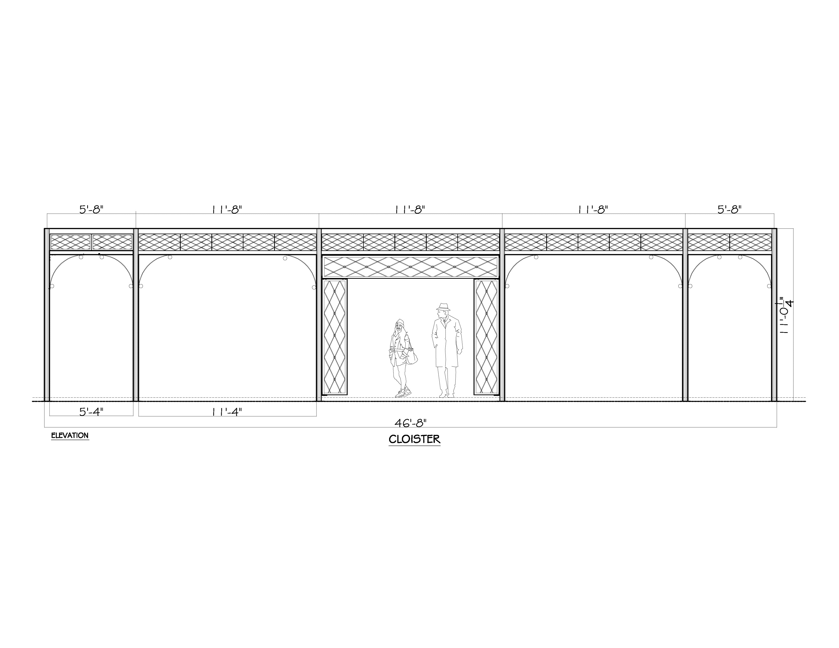
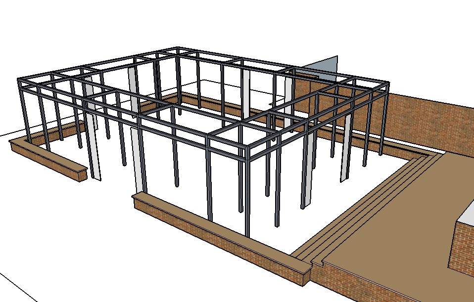
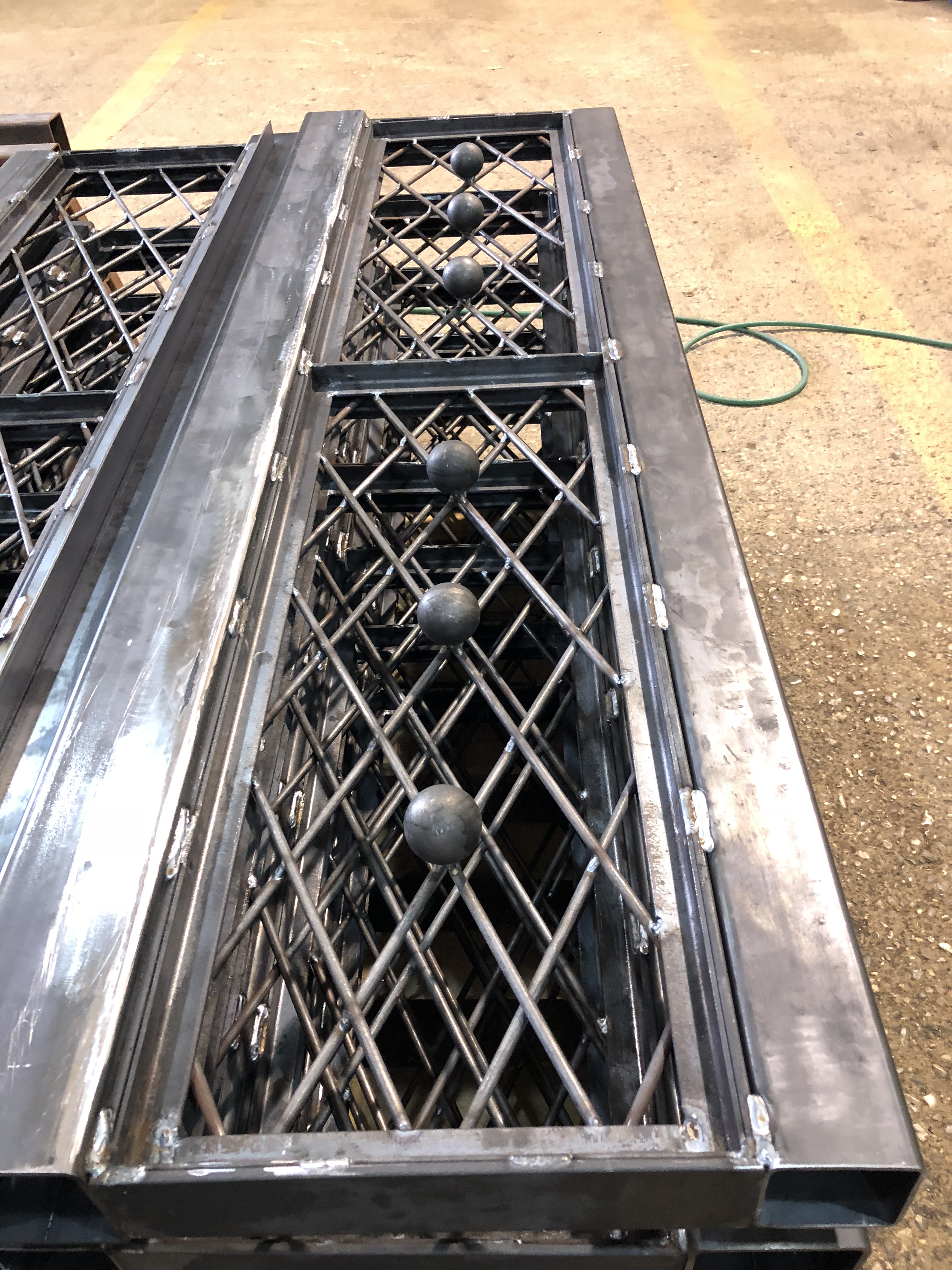
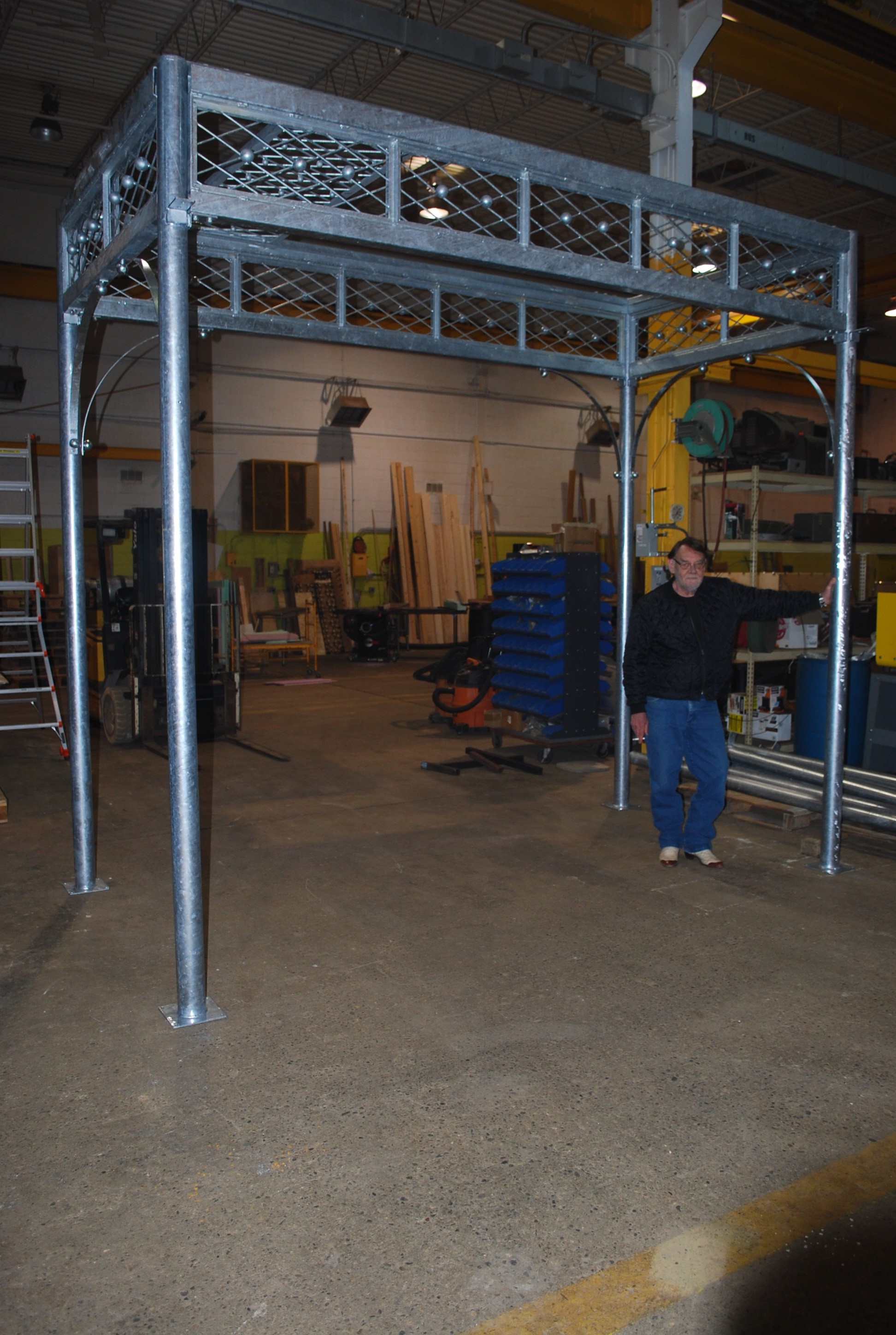
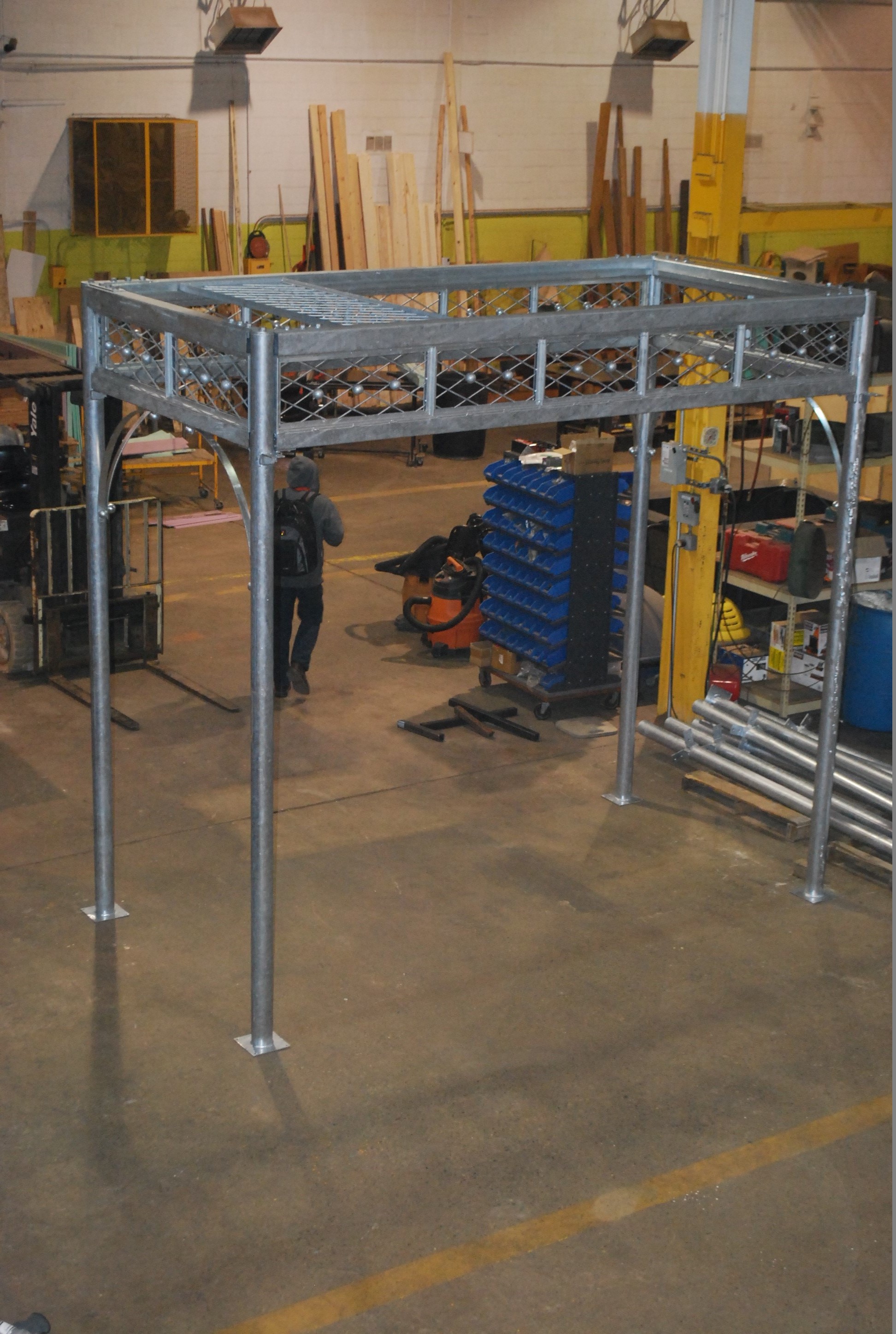
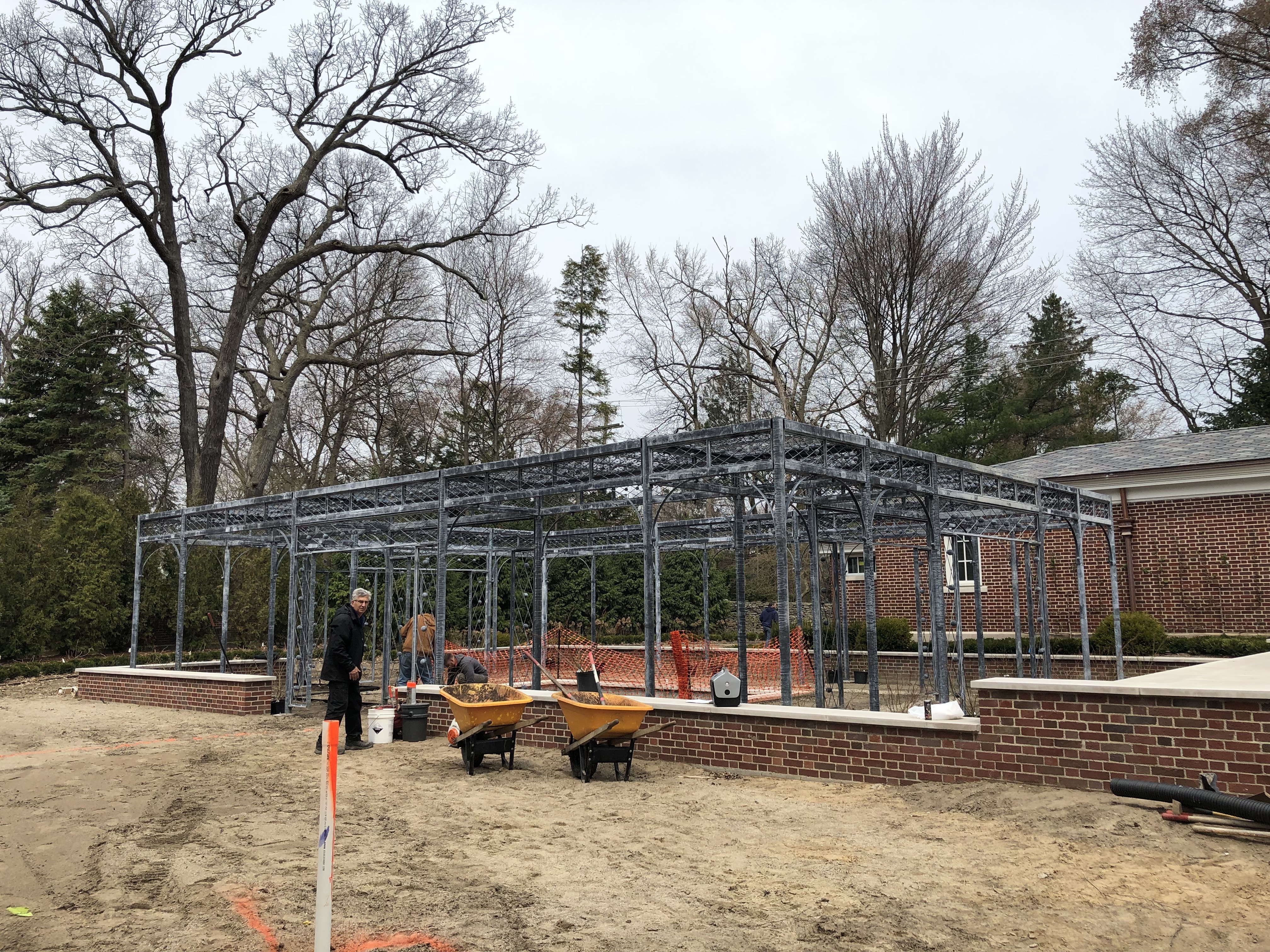
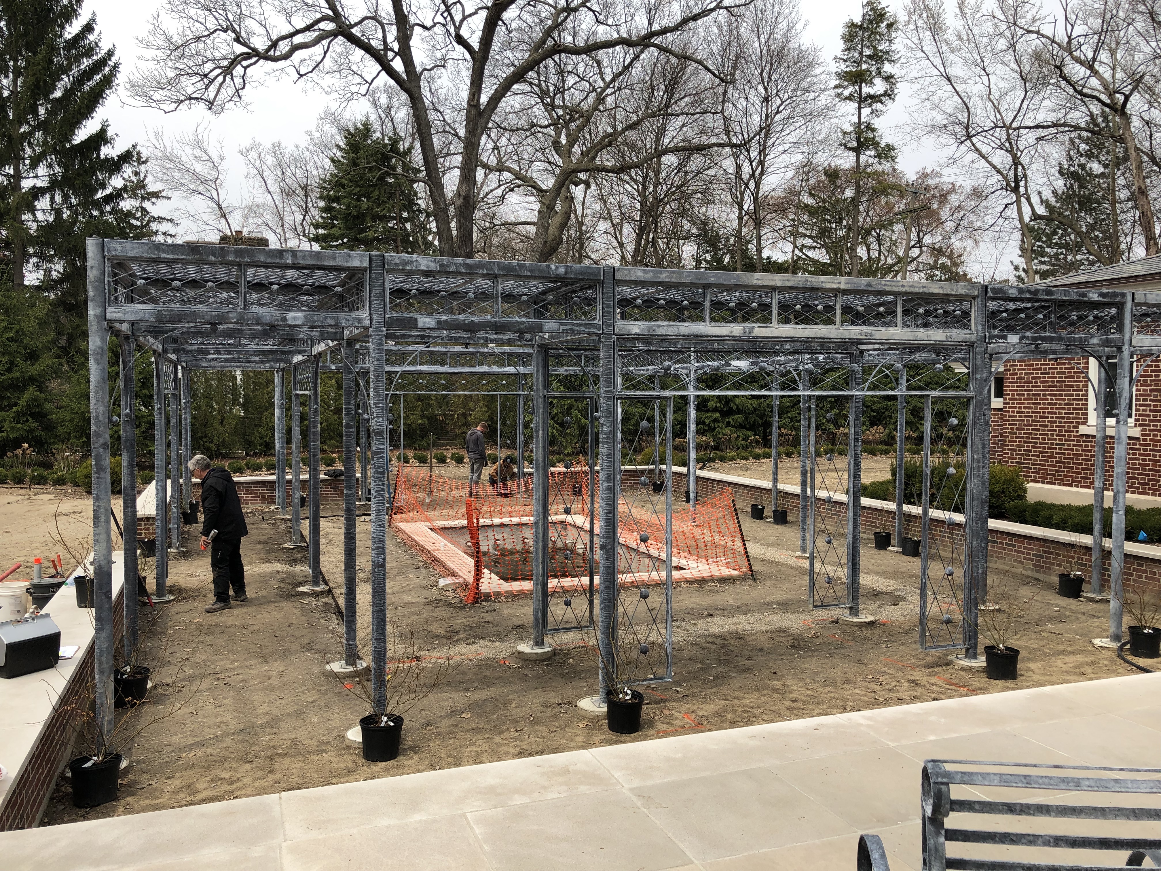
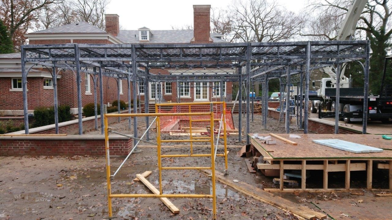 Cloister? In its simplest form, a cloister is a covered walkway. This structure has a six foot wide walkway all the way around the perimeter. That walkway is covered by roof panels constructed in an open and elongated diamond pattern. The cover will provide some shade, but will permit light and rain to come through. That pattern is repeated on the fascia panels at the top. There are 32 round columns, each of which is bolted to a concrete foundation that goes 42″ deep into the ground. Between each pair of columns is a pair of curved steel brackets. This curved detail compliments the roundness of the columns, and the solid steel spheres that ornament the structure.
 Buck’s first drawing of the cloister showed square columns. The look on his face when I told him that I wanted round columns was an unmistakable sign that I was asking for the moon. After he explained that engineering flat surfaces to perfectly line up and be attached to a curved surface would be just about impossible, I paused. The roof and fascia panels would be built from round rod, and each panel would feature steel spheres. The round columns would be essential in giving a structure of this size a graceful appearance. The architecture of this stately old home was not asking for an industrial look. Please? He relented.
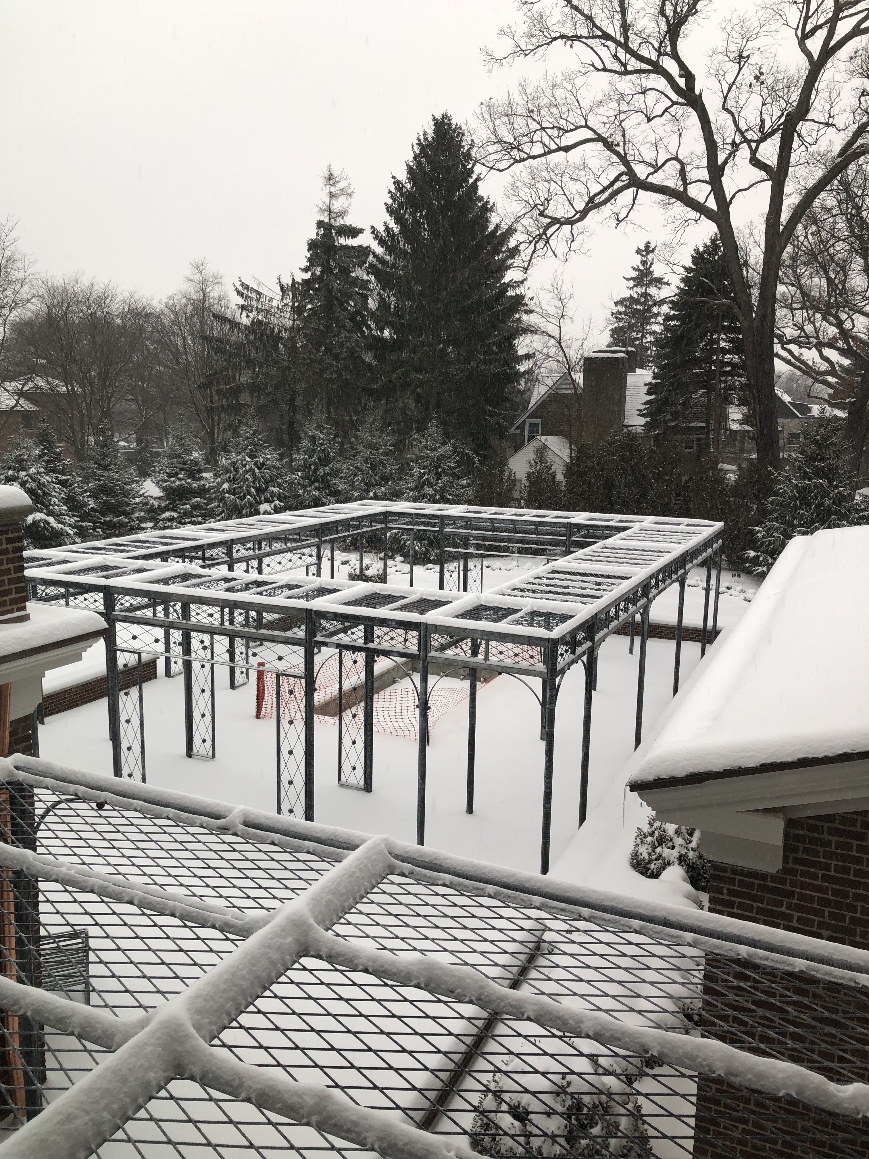 Buck did a superb job of engineering, and his group did an equally fine job of fabricating. My client took this photograph and the following one after a snow storm this past winter. I was delighted to see how the snow outlined and described every detail of the structure. It will be a feature of the landscape every season of the year. As planned, the cover over the walkway was permeable to both light and water. In the immediate foreground of this picture is the roof of a very simple version of the cloister over the dining and grilling terrace that is directly adjacent to the house.
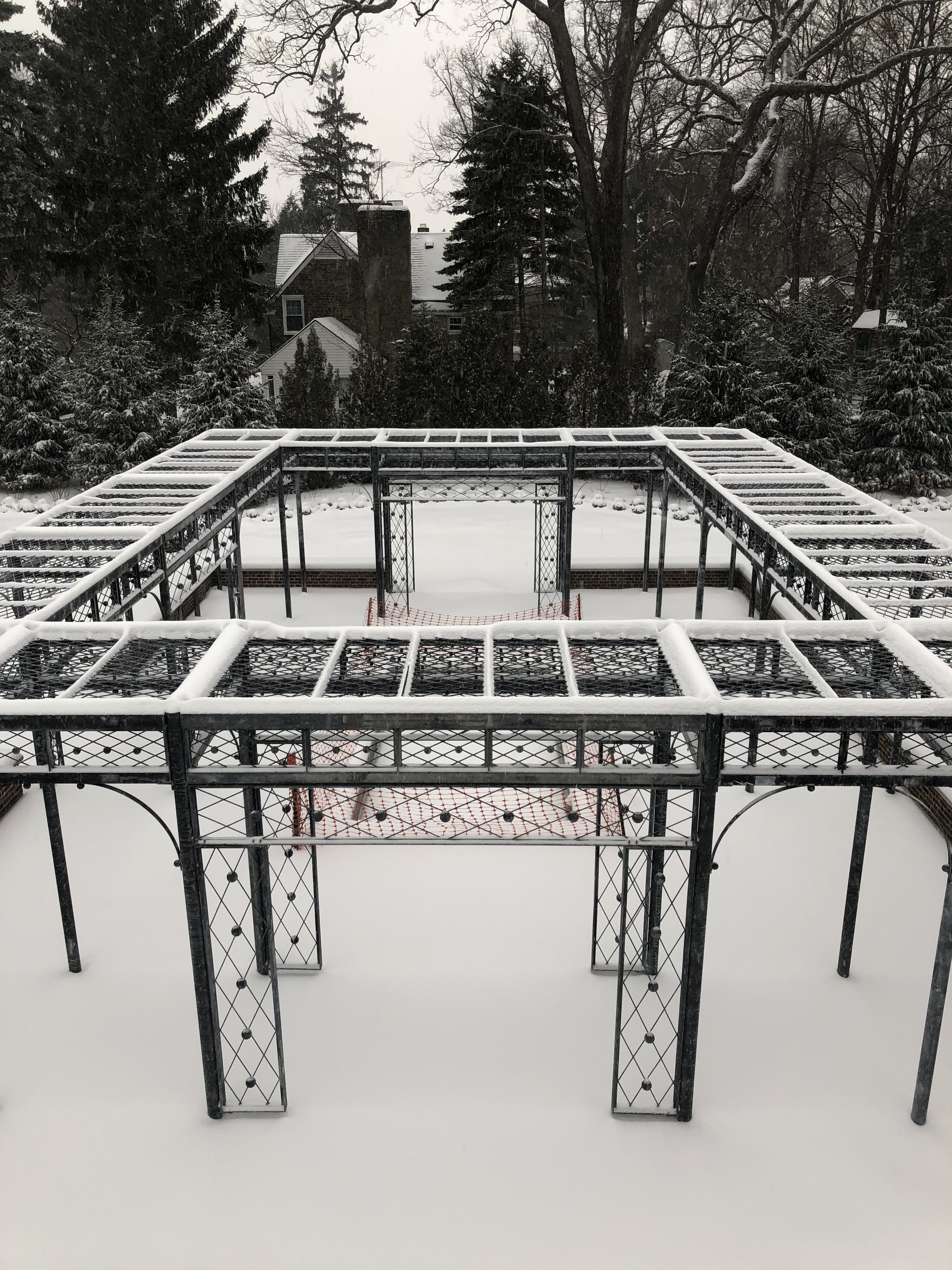 The snow made it easier to see the long diamonds and dots pattern on the roof, fascia panels, and the main entrances into the space.
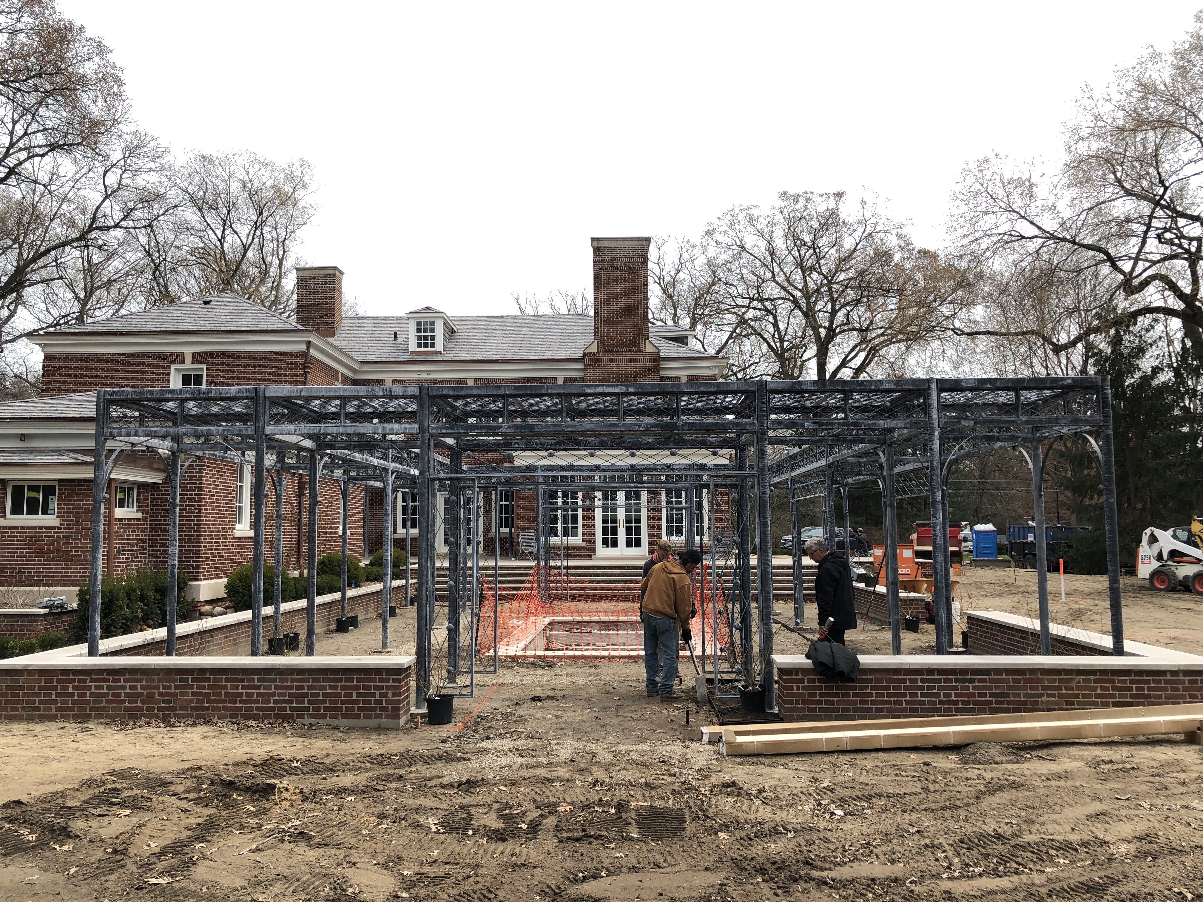
 Now that the long winter is over, we are back on the project. I have every confidence that come late May, this landscape will be ready for her to enjoy. We have little to do in the interior of the pergola. Bringing up the soil level to grade, planting the roses, installing the edger strip and grass is about it. The irrigation in this area is underway, and the tile for the fountain pool is due in May first.
 This was the first time I had seen the completed structure since the work began. I was thrilled with how it looked. And incredibly appreciative to have a client who made it possible. Their are limestone stepping stones yet to come. I had the roses custom grown several years ago. Dan and David have been growing them on, so we would have plants of some size from the beginning. The furniture and pots for this area have been in storage at our landscape building since last September. Though I will probably post about this project again when the landscape is complete, this is a very special moment for my entire group. The best part? Our client is pleased.


In the homestretch now.