 If you have been reading this series of posts, you will recall that my landscape design called for a rectangular cloister style pergola to be built off my client’s sun porch and garage. That shape was dictated by an L shaped space established by the sun porch, and the long back side of the garage. The center of that cloister would be a fountain pool. My drawing, pictured in the previous post, was schematic, meaning that drawing was a generic structure, just holding a place on the page. Once she indicated an interest in a pergola surrounding the fountain, I went to work to actually design that structure.
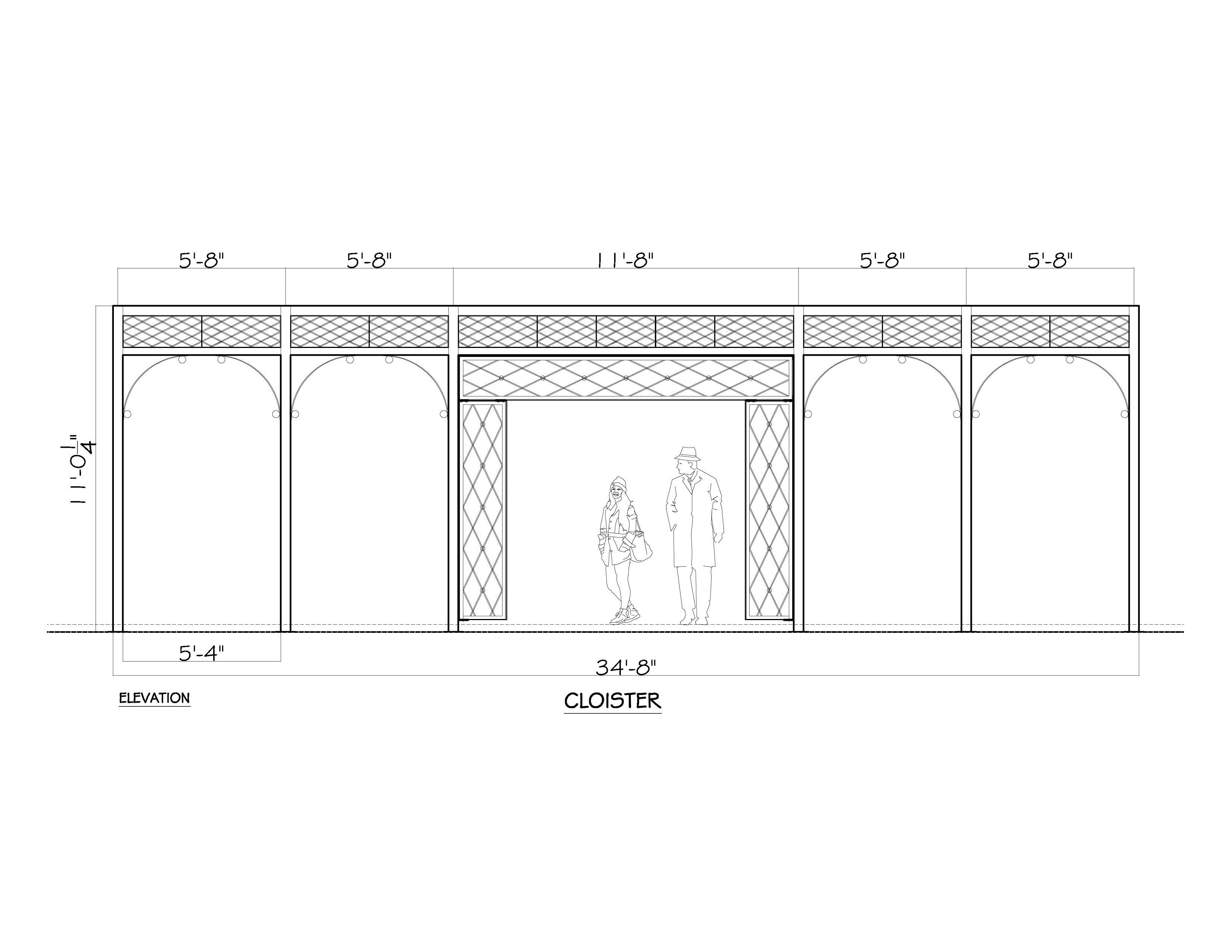
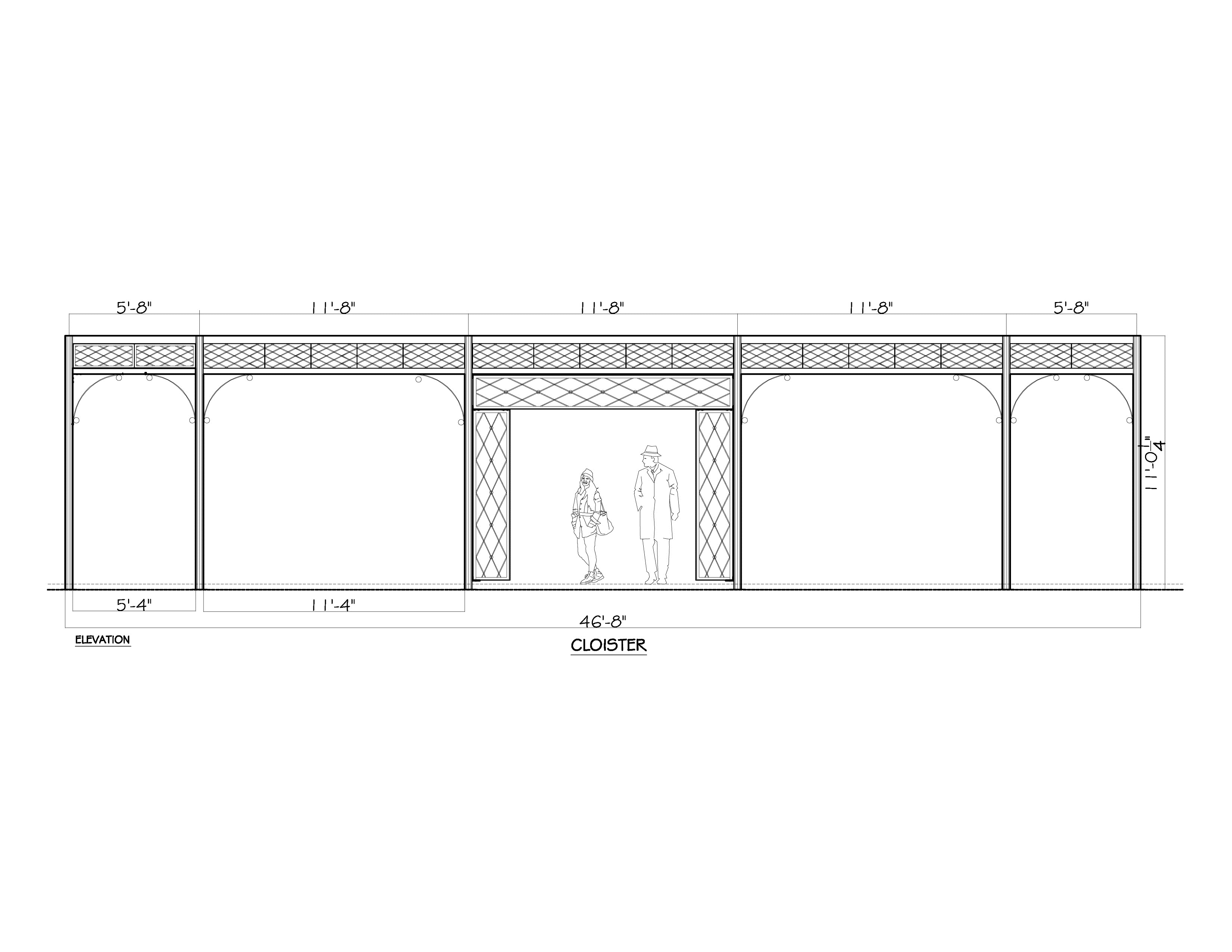 So what is a cloister? A cloister is a covered walkway, frequently surrounded by a building or buildings on all four sides. Historically, it was an architectural feature common in monasteries and courtyard spaces in universities. The design for this pergola is predicated on a 6 foot wide covered walkway which would provide overhead structure to the fountain pool. The photo above shows Buck’s CAD drawing of the long side, which is almost 47 feet long. The design revolves around a series of elongated diamonds of different sizes, and steel spheres of 3 sizes. Buck added some figures to his drawing, so I could see what the relationship would be between person and structure. A good part of the reason it is 11 feet tall is its placement. Standing at the bottom of five steps from the sun porch grade, it was important that the roof did not appear too low from that vantage point. That height will also give it some presence from the upstairs windows, and the balcony which is on top of the sun porch roof.
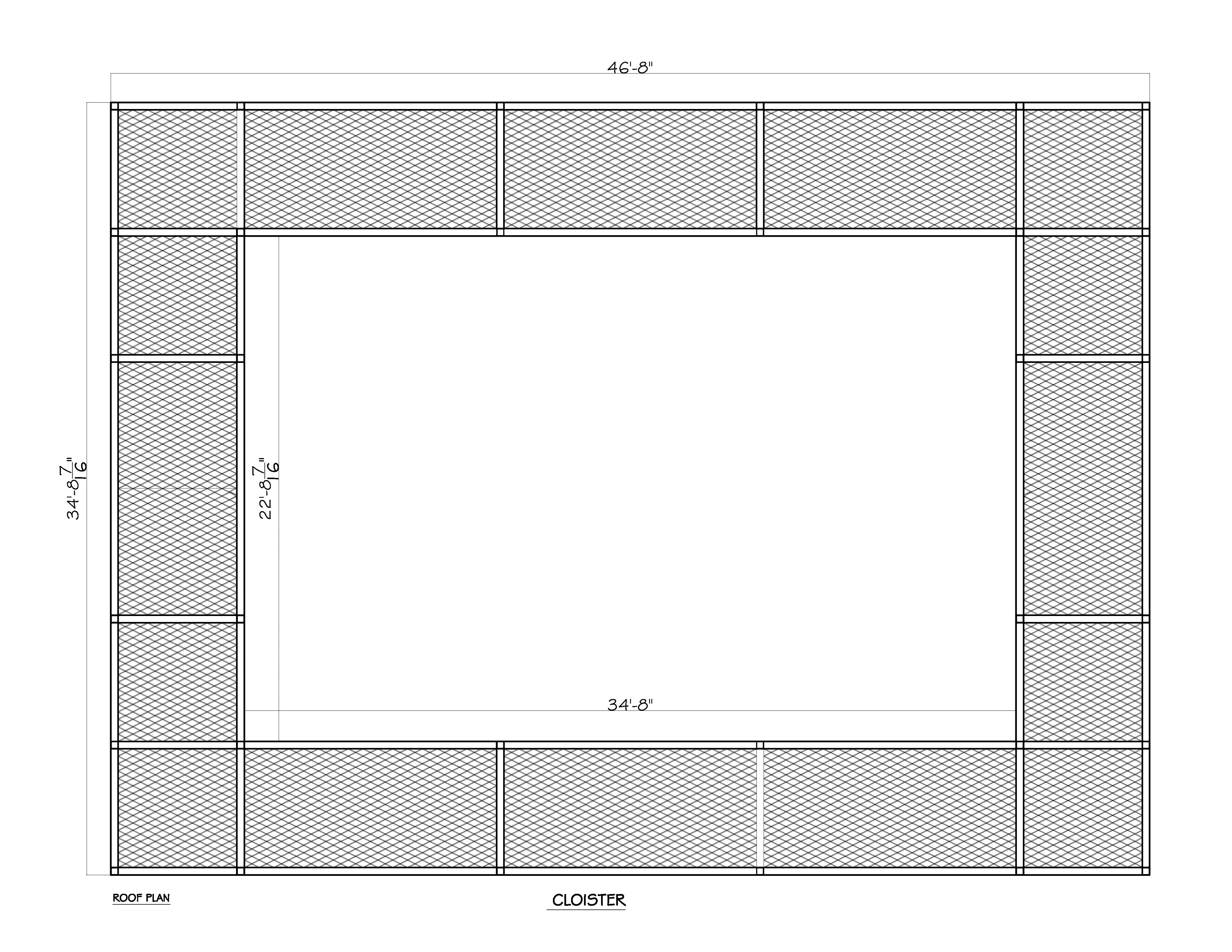 This drawing of the roof panels makes clear the idea of a covered rectangular walkway. And that the interior space would be open to the sky. It was almost a year ago that we ordered the John Davis roses that would be planted on the pergola columns. I still have hopes of putting them in the ground yet this year, but if not, we can winter them over in our landscape building.
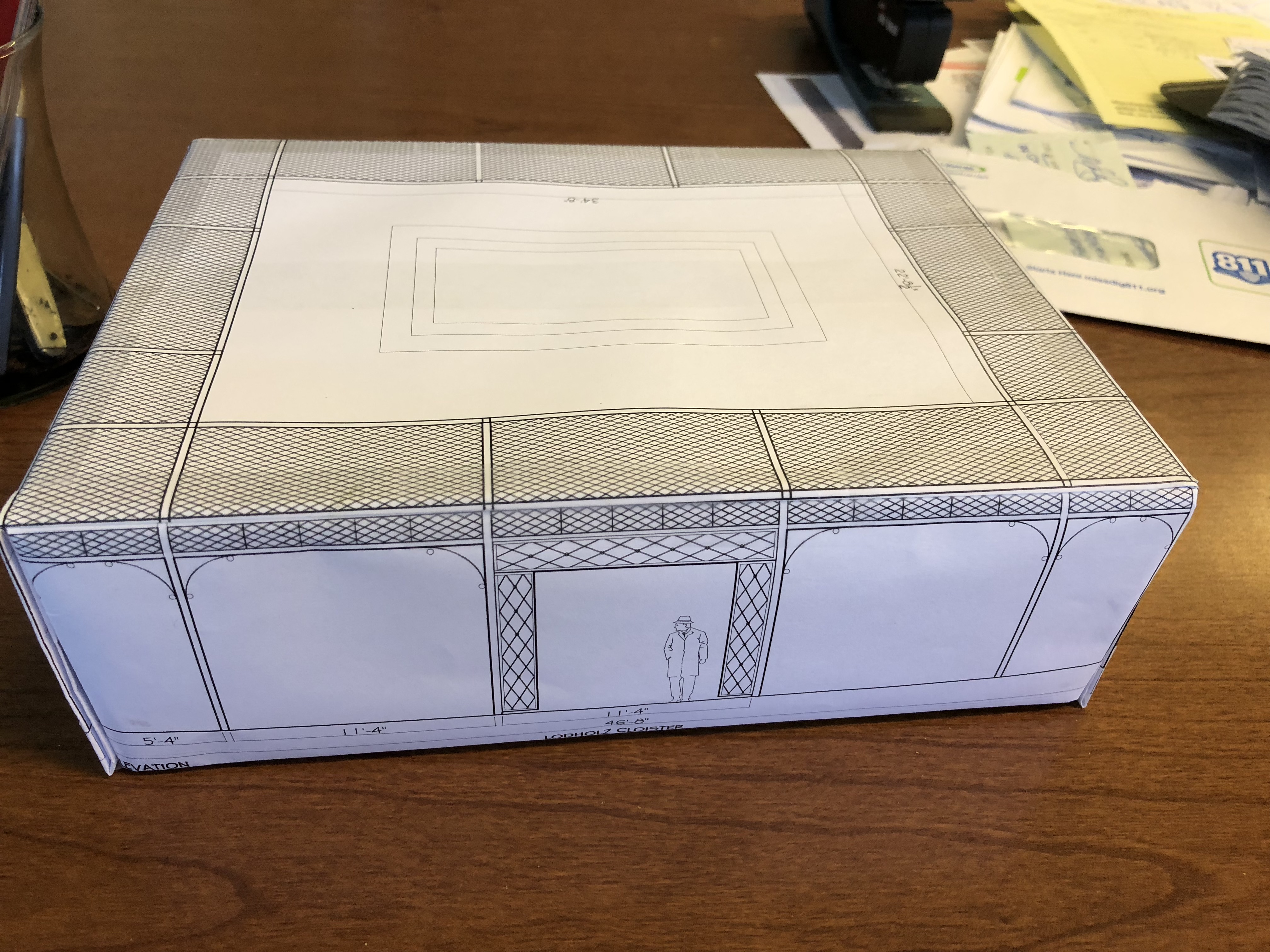 The drawings are useful to a designer, but maybe not so much to a client. Buck figured out how to scale the three drawings the same, and I built this model from sheets of copy paper. Buck drew the schematic for the pool on the roof plan. All of the white spaces on the paper will be open spaces.

This model came months after the presentation of the original plan. Once my client approved it, there would be much more work to come. Not only were there engineering issues to sort out, all of the dimensions would have to be coordinated with Mike Newman, as his steps and walls were an integral part of the installation. The following drawings were passed back and forth between Buck and Mike, so all the the locations and dimensions could be mutually agreed upon before anything was built.
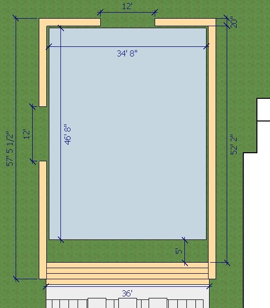 This plan view of he steps, walls, and pergola show the relationships between the various elements. The walls would have 2 12′ wide openings that would provide access to the back and side yards. Upon reaching the bottom of the stairs, there would be 5 feet of open space before reaching the pergola.
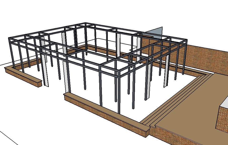 These drawings do the best job of illustrating the fact that there are pairs of columns that would hold up the roof. There are 32 in all. And the columns are round. I designed as much of this pergola to feature round shapes, as opposed to square or rectangular. The round shapes seemed less industrial, and more fitting to the period of the house. Buck said this decision made the engineering much more difficult, but I think it will prove to be well worth the trouble.
 view from above
 view from the far end
 the view of both exits
 Pictured above is a group of the roof panels, after the galvanizing process. The round rods are captured in a square steel channel. The solid steel spheres, welded at the juncture of every other diamond, will face down. There are 2000 of them, in all.
 These fascia panels feature a larger gauge steel rod, and 2″ diameter solid steel spheres. These are finished panels in their raw steel state.
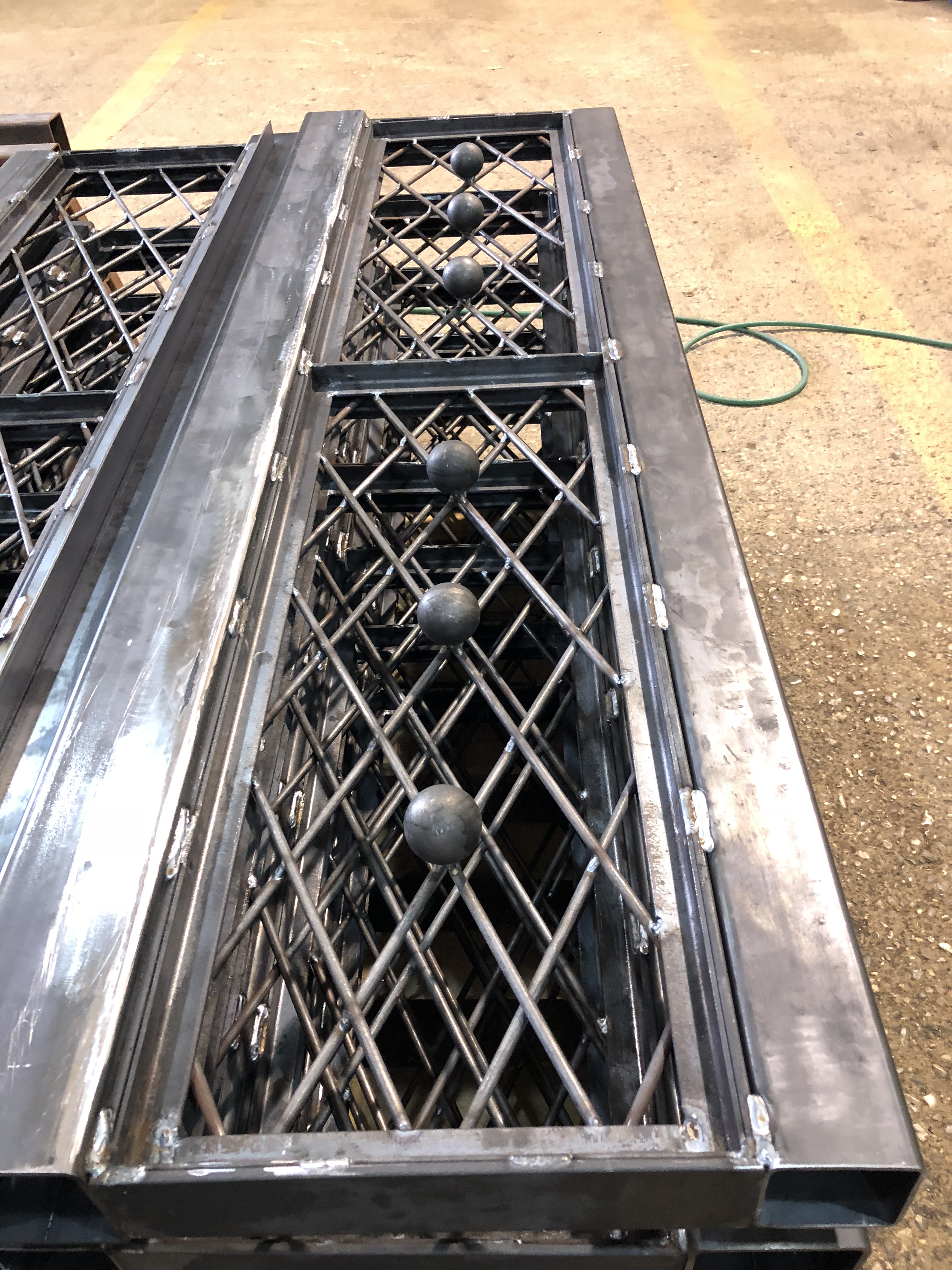
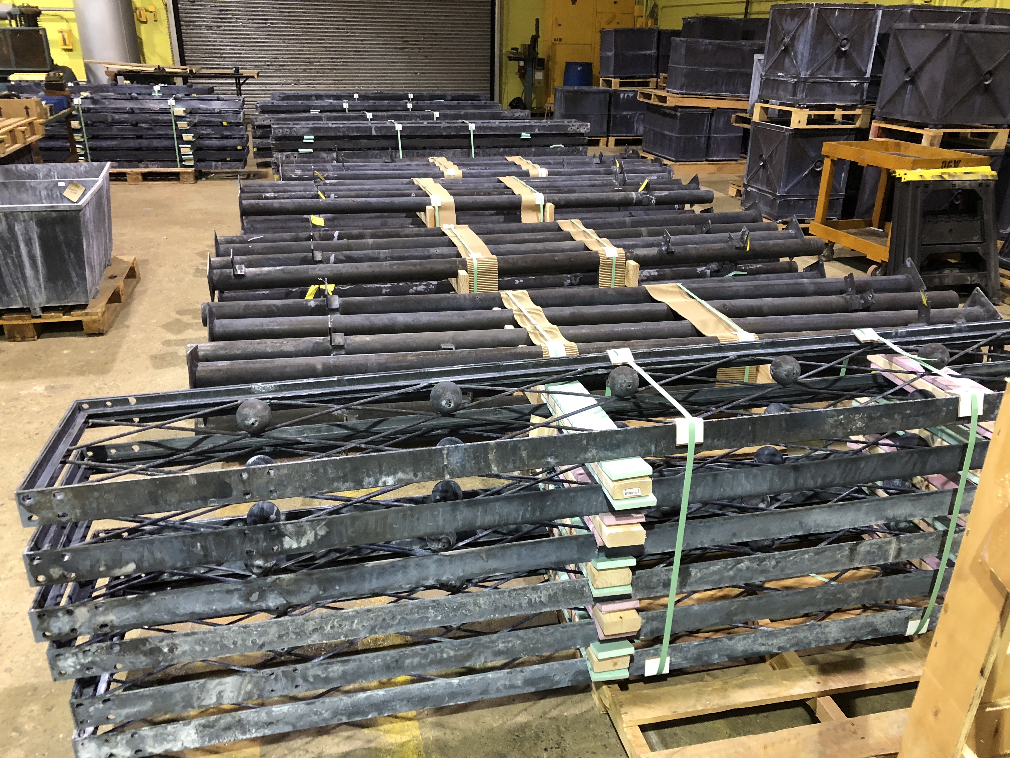 The pallet in the foreground is stacked with the pergola entrance panels. These have the largest diamonds, and 3″ diameter steel balls. In the background, pallets full of columns.
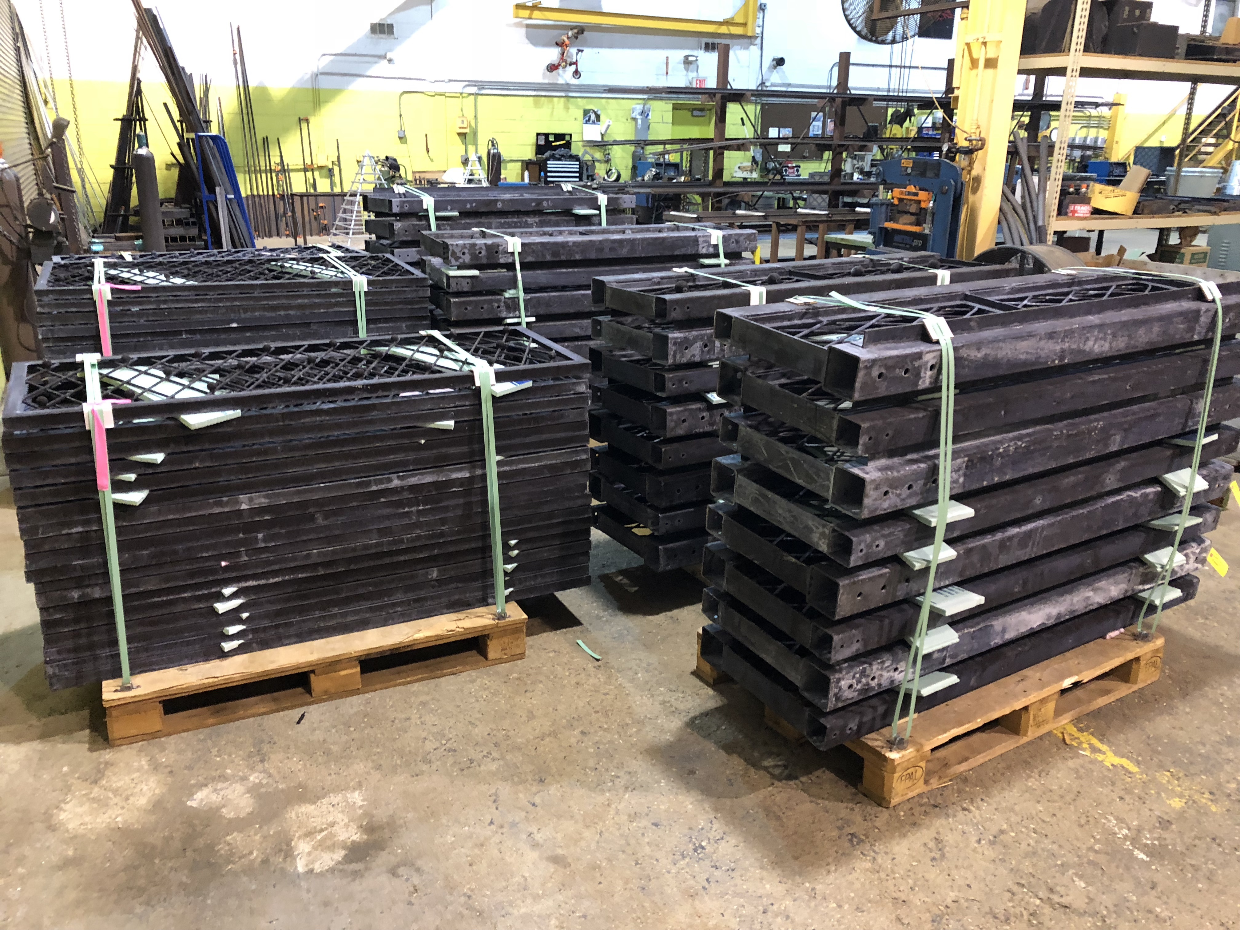 Branch limited the weight of every pallet so it would be easy to offload them at the site.
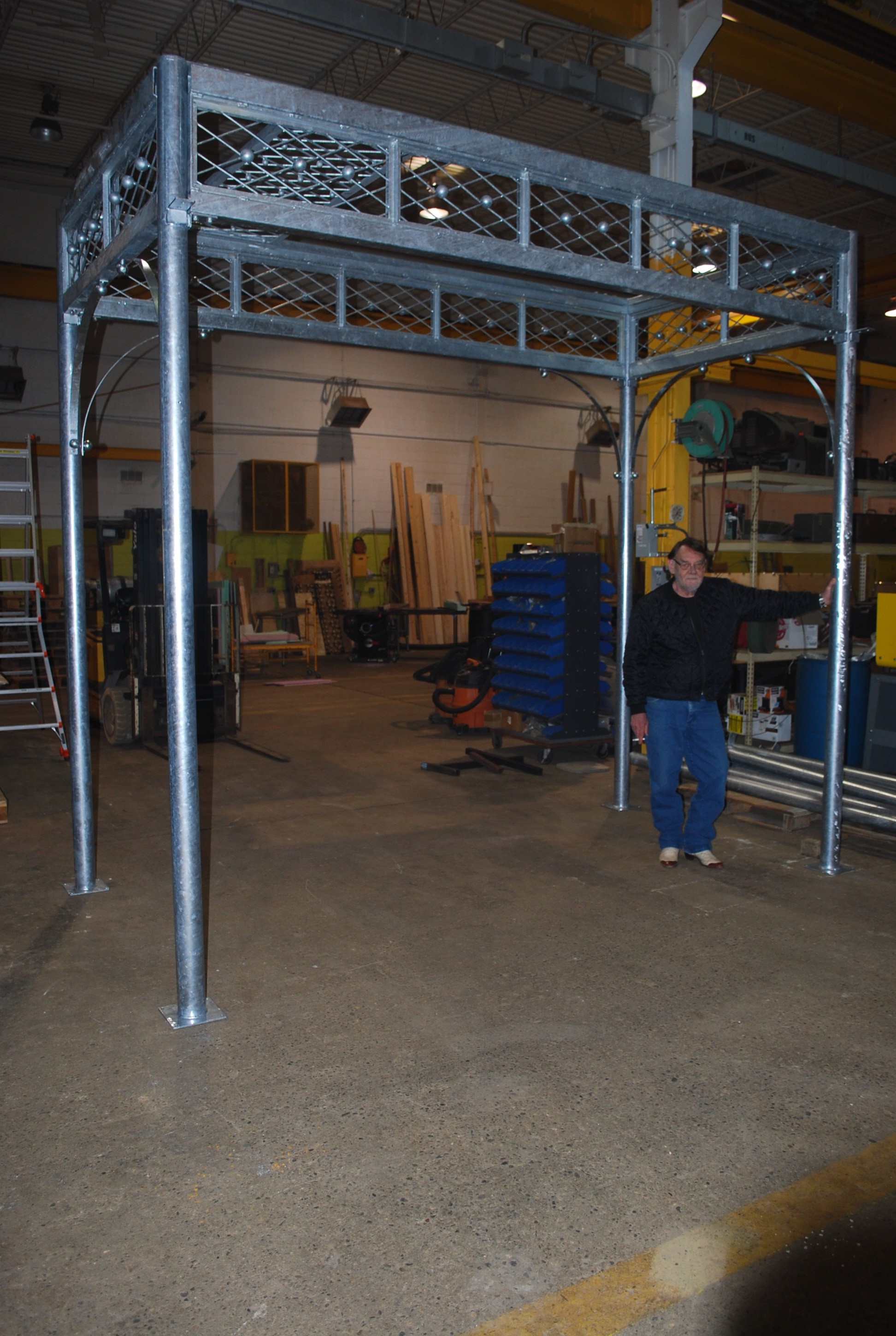 Prior to loading up the pallets, Buck had his guys pick random pieces from each stack of parts, and had them put together one 12′ by 6′ section. He wanted to be sure all of the parts would go together easily. Putting a pergola together in the field is a much different operation than putting it together in a warm dry shop, with a bridge crane overhead. The install will be lengthy, as it is a big structure. Maintaining the precision with which each piece was fabricated was a challenge. That precision is what will make the install go smoothly.
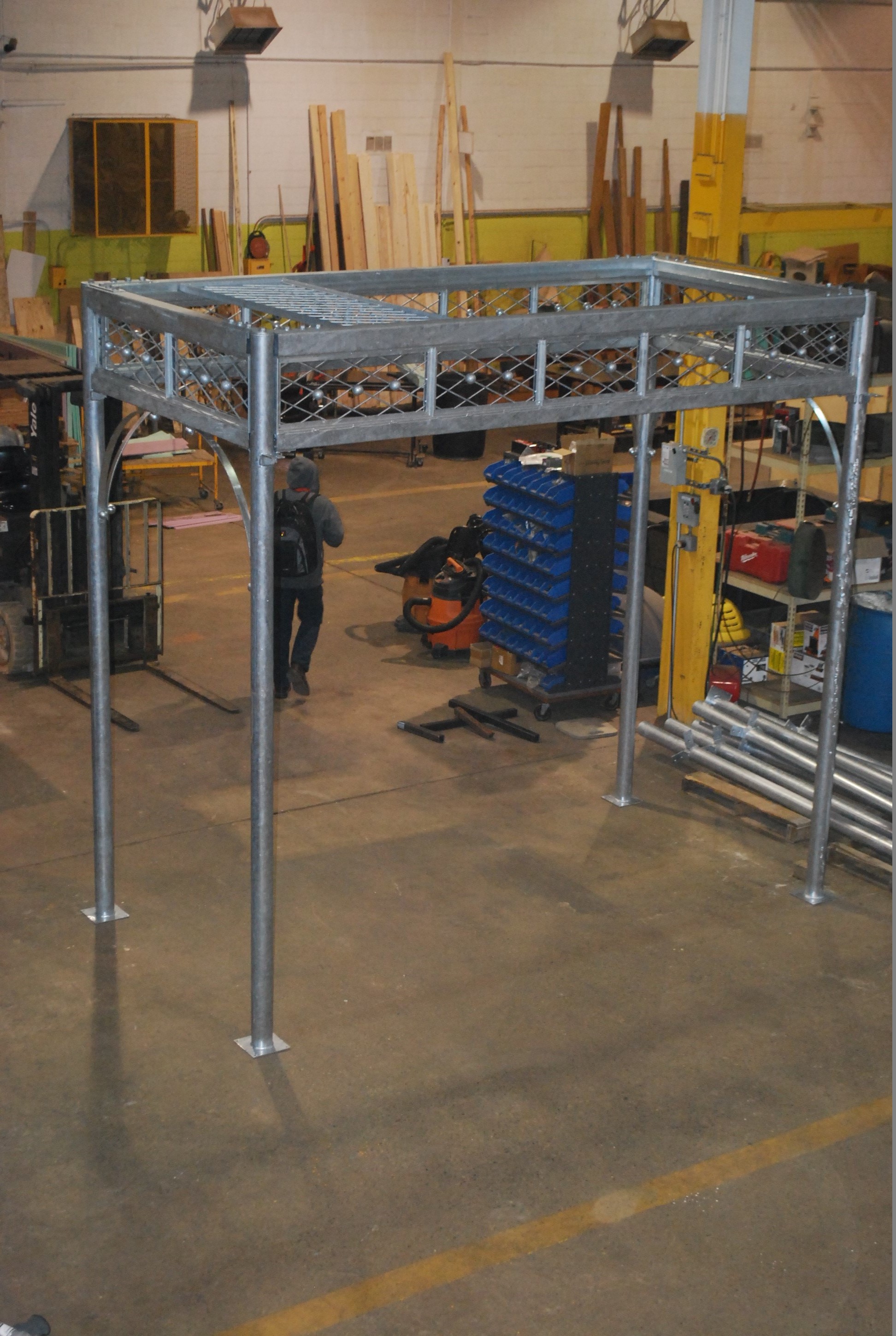 This view from the mezzanine at Branch shows a roof panel set in place.
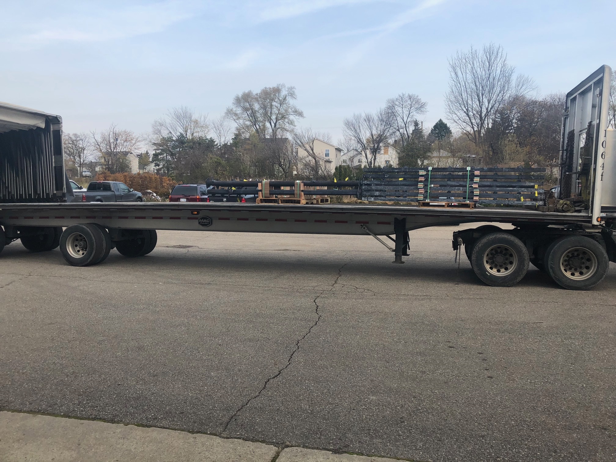 Jackie arranged for a dedicated flatbed truck to transport the pieces to the job. Even so, there were 6 pallets left over that my landscape crews loaded in their trucks. None of the pallets could be stacked.
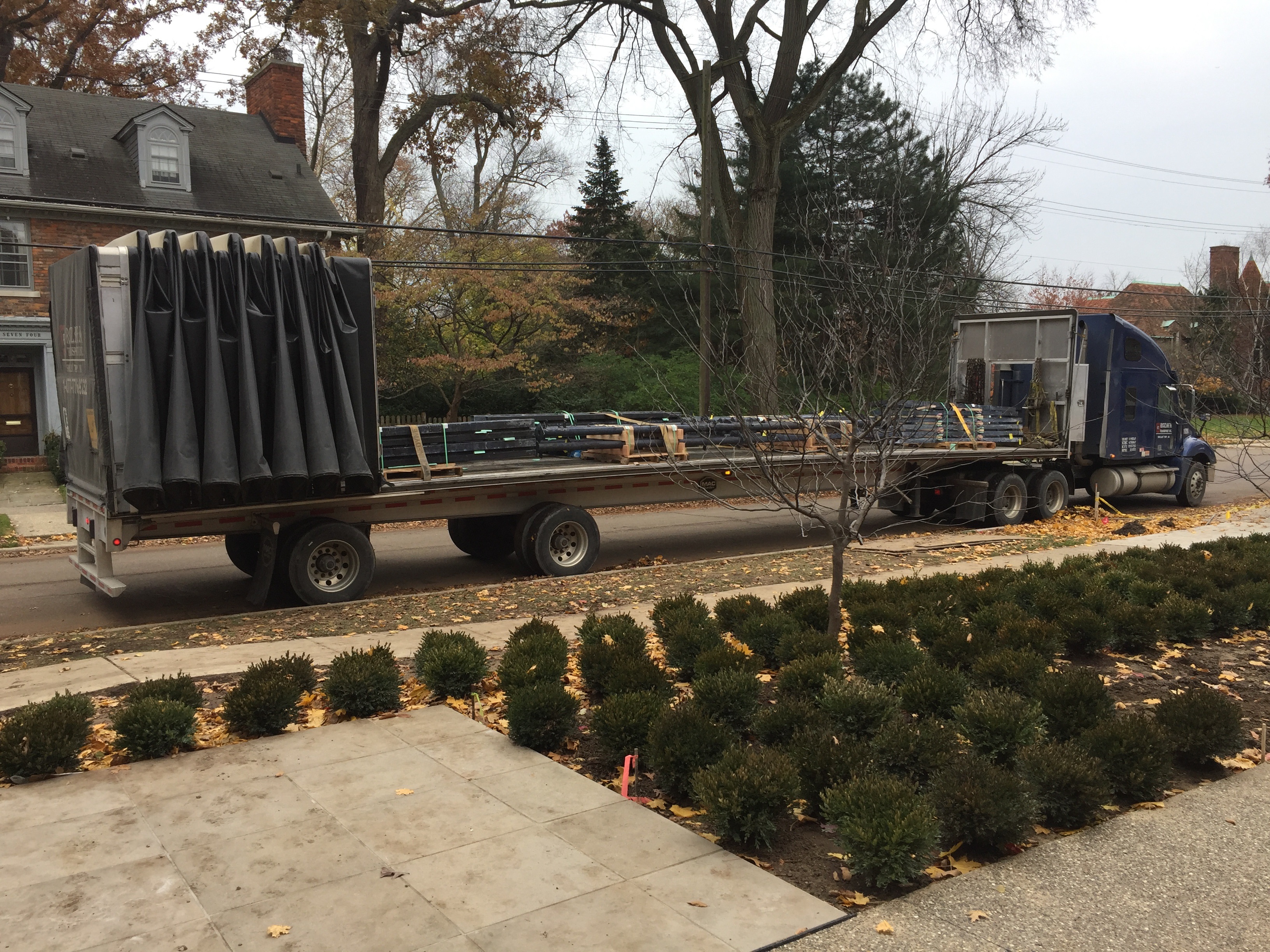 We had our loader on site, so we could offload once the truck arrived.
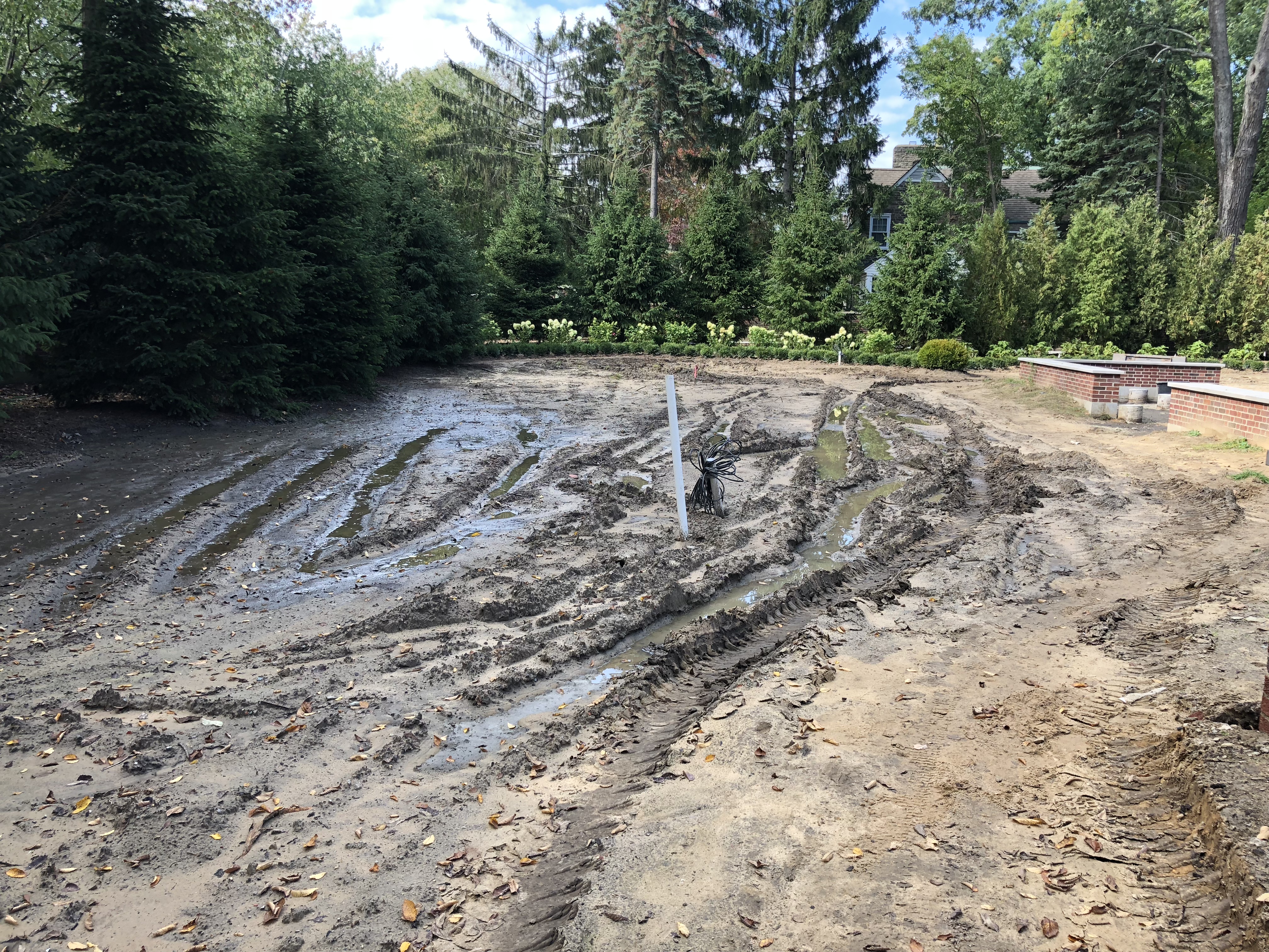 There was one part to the story we did not anticipate. 3.5 inches of rain fell in the area where the boom truck would be located, and those pallets would be staged. We had not gotten to a finished grade in this side yard. The ground was very low here. Our original delivery and installation date came and went. I was not pleased with the prospect of having to waiting until the ground froze. I put in a call to my large tree contractor, and asked if there was anything he could do.
 Ralph brought in 80 yards of sand, and 100 sheets of 3/4 inch thick plywood, with the intent of building up the grade such that we could access the site.
 He built a road in that would be able to handle the weight of the pergola pieces, and trucks. Fortunately, this side yard is still so low, that all of that sand will eventually become part of the finished grade. He is estimating he will need another 200 yards of soil to bring this space up to grade.
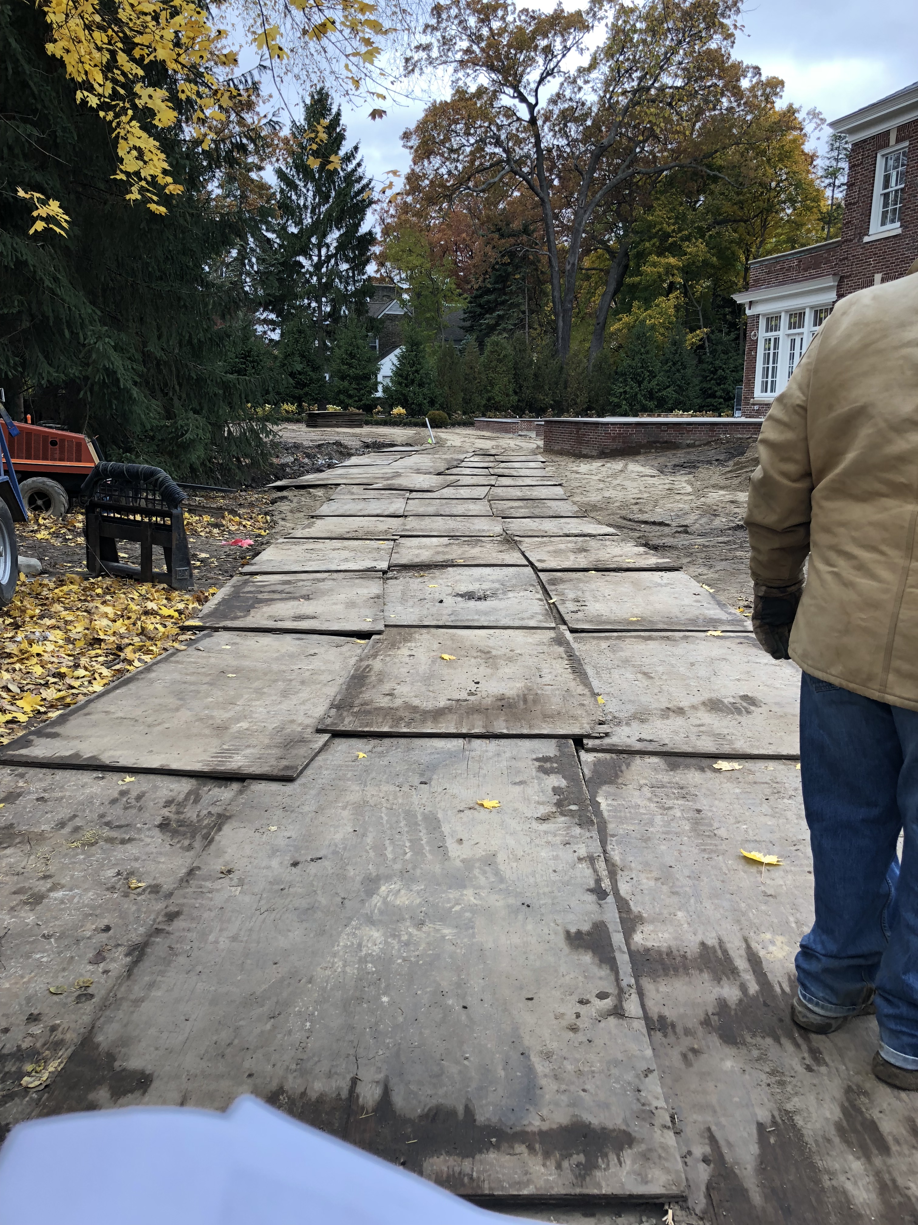
 The boom truck is an incredibly heavy piece of equipment, featuring a large arm that will pick up each piece in the proper building order. That truck has huge steel arms that come out, and rest on the ground, to stabilize the truck. Plywood and sand would not be enough to keep that truck stationary. The construction mats you see in the above picture weigh 1000 pounds each. Ralph assured me that they would stabilize the ground for any truck we needed to get back there.
 finishing up the road in
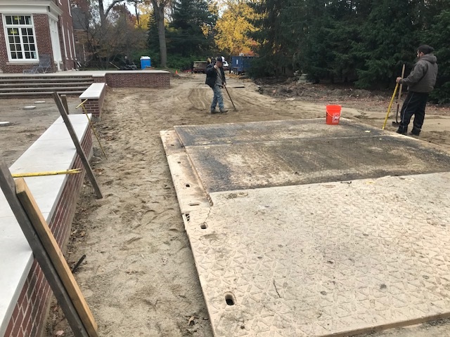
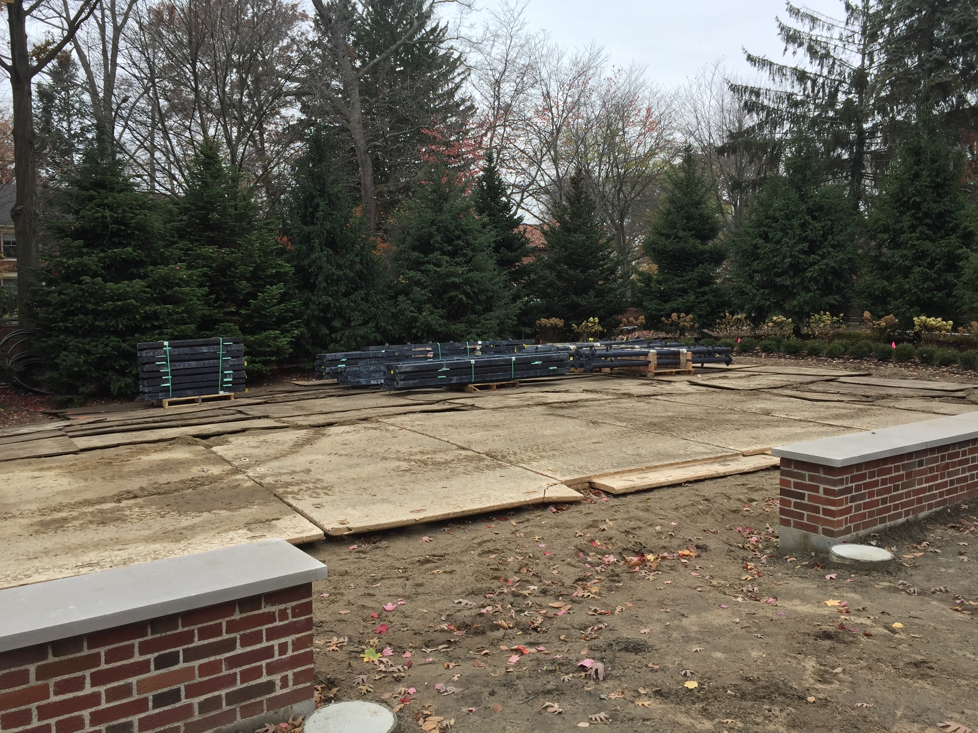
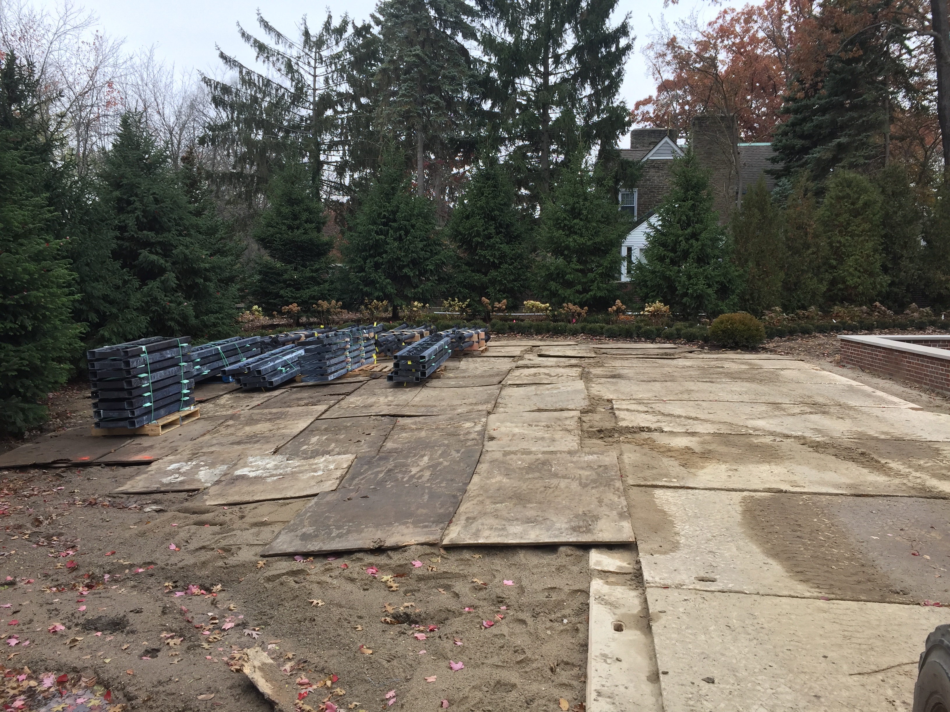 Sheets of plywood were all we needed to stash the various pallets. The boom truck operator will be able to pick up any part he wants, when he needs it. It took 3 days to get the site ready. Templeton Building Company will do the actual installation. Buck will be there the first day, to advise.
 Everything is ready. The boom truck is scheduled to arrive this afternoon. I hear the scaffolding is going up now. Each column will be bolted to the footings that Mike poured some time ago. The structure will be bolted together, one piece at a time. It could take a week, from start to finish. For now, I am just very happy to know we are in the home stretch.